Continue to Site

Eng-Tips is the largest engineering community on the Internet

Intelligent Work Forums for Engineering Professionals

  • Congratulations waross on being selected by the Eng-Tips community for having the most helpful posts in the forums last week. Way to Go!

Steel Column Reinforcement 1

Status
Not open for further replies.

Eng_Struct

Structural
Sep 23, 2022
56
Hi All,

I have an existing 9.7m tall column that is HSS 300 x 300 x 6.4. Due to the additional weight added, I am finding my column to be overstressed by roughly 20%. The column is failing due to flexural buckling. I will need to provide reinforcing plates on all four sides to increase the radius of the gyration to increase the section capacity.

However, I am wondering if I need to reinforce the column for the full height. Can I not just provide additional reinforcing midway (i.e, reinforce only 4.850m from the ground) to reduce the unbraced length. Analyze the top section based on the 4.850m section for the flexural buckling and check the bottom section with reinforced section properties. Note that the load to the column will be coming form the very top.

Any watch-its or things to be concerned about for the above-mentioned reinforcing stratergy? Also, what do I need to consider for the weld design and spacing for the reinforcement?

Thanks!
 
Replies continue below

Recommended for you

1) You can absolutely reinforce partial length. Two options that I've used for this:

a) Treat it as a stepped column and do the hardcore checks via fancy math or a true buckling analysis using your preferred software. I rarely do this.

b) Run the reinforcement over at least the middle 70% of the column and call that good enough. I often do this.

2) I prefer channel reinforcing for this over plates but either can be made to work.

3) Where the reinforcing starts and stops, I think it prudent to provide localized welding to move an amount of load into the reinforcing in proportion to the area of the reinforcing divided by the total area of the built up cross section. Stitch weld in between to make the combined cross section buckle in unison.

4) If you won't be relieving the column of it's existing load prior to reinforcing it, as I expect, give some consideration to the implications that will have on the stresses in the column.

5) With partial reinforcement, you need the squash load to check out over the unreinforced bits (phi x As x Fy). It sound as though this won't be an issue in your case.
 
Good response Koot... pretty much what I've done...

-----*****-----
So strange to see the singularity approaching while the entire planet is rapidly turning into a hellscape. -John Coates

-Dik


If i were in your shoes , i would consider concrete filling of HSS 300 x 300 x 6.4 to get composite behavior ..


If you put garbage in a computer nothing comes out but garbage. But this garbage, having passed through a very expensive machine, is somehow ennobled and none dare criticize it. ( ANONYMOUS )
 
 https://files.engineering.com/getfile.aspx?folder=7bbcb06f-80aa-4478-a64c-c01faed09041&file=bzdawka_composite_column_calculation_WORKED_examples.pdf
Thanks Everyone!

I also came across a presentation on AISC where they noted a solution to check the capacities of partially reinforced columns.

As I understood, they have calculations to come up with the equivalent effective length of the column that is larger than the actual length, to be used to check the capacity of the column using reinforced section properties and also check the capacity of the unreinforced section. I think the reasoning behind using a larger length for the reinforced section is to account for the fact that portion of the column (unreinforced section) is weak.

Screenshot_2023-01-30_140258_bjsf2p.jpg


If interested, you can find the pdf attached.
 
OP said:
I think the reasoning behind using a larger length for the reinforced section is to account for the fact that portion of the column (unreinforced section) is weak.

The reasoning is that it's simply another way to accomplish this, in canned form:

KootK said:
a) Treat it as a stepped column and do the hardcore checks via fancy math or a true buckling analysis using your preferred software.

"Weak" needs to be viewed in the context of the failure mode being considered. The entire length of the column will buckle together so, for buckling, it's more accurate to think of the partial reinforcement as simply reducing the flexural stiffness of the entire, reinforced column a bit relative to the stiffness that you would have had if the reinforcement ran the entire length of the column. It is primarily this stiffness that provides your buckling resistance.

OP said:
...and also check the capacity of the unreinforced section.

Note that the adjusted length business alone does not check this, important aspect of the capacity of the unreinforced column segments:

KootK said:
5) With partial reinforcement, you need the squash load to check out over the unreinforced bits (phi x As x Fy). It sound as though this won't be an issue in your case.

OP said:
If interested, you can find the pdf attached.

Thanks for sharing. You'll find a bunch more similar information in this thread from November of last year: Link
 
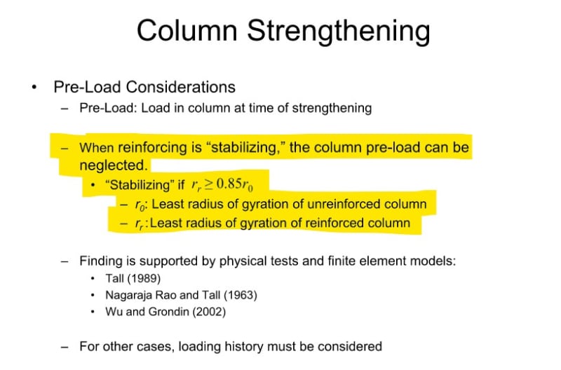
Further to your comment regarding pre-loading KootK, I came across the following from the AISC webinar for steel strengthening. They have noted that the pre-loading can be ignored if the reinforcing is "stabilizing" and meet the noted criteria. I am not sure what "stabilizing" mean. I also did come across a few research papers noting that the pre-load had little effect on columns governed by flexural buckling, or flexural-torsional buckling.

I will like to consider the AISC condition for my compression member reinforcement for future projects. However, I will like to understand the rationale behind this.

Screenshot_2023-01-31_083842_jautdj.jpg
 
Welding steel plates to a column will cause weld-induced distortion. This distortion is large if you weld badly (one long weld) and with too thick welds, and small if you weld in a smart manner (stitches and then filling the intermittent parts) and with a suitable weld size. Welding specifications (which affect heat input and thus distortion) are also important. If the column is loaded, the above mentioned distortion can cause p-delta effects.

As far as the AISC figure goes, it states that "stabilizing reinforcing" does not greatly change the smallest radius of gyration of the column. If your column is symmetrically reinforced in each cross-section (or reinforced along the entire length), that is automatically satisfied, so I'm not quite sure of the use of that criteria.
 
OP said:
However, I will like to understand the rationale behind this.

When considering this, mentally replace ry with SQRT(Iy/A). The intent is more transparent that way.

This is best illustrated by considering two, extreme cases:

1) CASE 1: reinforcement is accomplished by increasing the area of the column receiving axial stress to a greater, relative degree that increasing the flexural stiffness. A ridiculous example might be reinforcing a wide flange column against Iy buckling with a couple of round bars welded to the web. This would increase the cross sectional area of the column but to little to improve Iy. This setup, obviously, would be very sensitive to how much stress goes where, when. Less good.

2) CASE 2: reinforcement is accomplished by increasing the flexural stiffness to a greater, relative degree than increasing the cross sectional area receiving axial stress. A practical example might be reinforcing a wide flange column against Iy buckling with a couple of plates running across the flange tips. This would increase Iy substantially and is a much stronger form of slender column reinforcement in many cases. This setup would be less sensitive to how much stress goes where and is the justification for the recommendation that you mentioned above.

I actually practice an extreme version of this method in most cases. I didn't mention it earlier because I didn't want to muddy the waters needlessly with "me" stuff. I like to reinforce slender columns like this:

a) Assume that the reinforcement take none of the axial stress.

b) Assume that the reinforcement only improves Ix/Ix with respect to the code design checks.

c) Connect things for strain compatibility as I mentioned previously.

Under this scheme, the reinforcement could be located in the next state so long as the reinforcement and the column were made to buckle in unison somehow.

This also speaks to my previous recommendation with respect to using channels rather than flat plates. The flat plates may well work but, in this respect, channels would tend to work better.
 
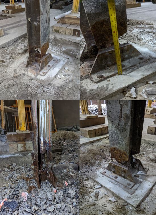
I'm on a job right (as the fabricator) where we are strengthening some corroded building and garage columns. Since it's reasonably related thought I'd share some of the details.

Here are some typical conditions. Scary that some of these columns were (are) supporting a 4 story building. IMHO I probably would have gone with complete replacement rather than the reinforcement. I imagine the EOR shy'd away from that since it reconciles you to have to shore the building for the design loads, which would be more expensive than what they did (they picked up the framing members just beyond the columns at the basement level only and shored to the SOG).

Columns1_uhe1aj.jpg


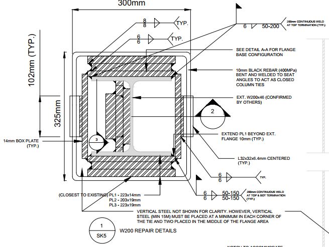
This is the repair. Lots of jogging out of plates to by-pass fastener heads and base angles. I had the existing steel tested and fortunately was confirmed to be weldable.

Columns2_ruuwti.jpg


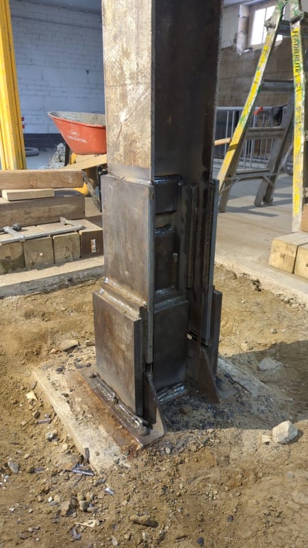
Picture of it in-progress. I don't particularly love the transverse weld we did at the top of the first flange plate for obvious reasons but we did it because the EOR wanted one (I would have just made the plates longer to get the required weld). I didn't push back on it because after seeing the columns I'm pretty sure whatever load they had originally is already somewhere else, and as a result wasn't too concerned about disturbing the (non-existent) stress field. That said, to mitigate the issue somewhat we welded the verticals first, then we welded half of the transverse weld, let it cool and then welded the other half. If I had been super concerned about the stress field I would have tapered the plate or said no to that kind of weld all together.

IMG_20230131_142139_021_lixrpl.jpg
 
Status
Not open for further replies.

Part and Inventory Search

Sponsor