Continue to Site

Eng-Tips is the largest engineering community on the Internet

Intelligent Work Forums for Engineering Professionals

  • Congratulations GregLocock on being selected by the Eng-Tips community for having the most helpful posts in the forums last week. Way to Go!

Can Basic Dimensions Be Overdefined? 3

Status
Not open for further replies.

G_Apache

Mechanical
Jul 7, 2022
6
Hi all,

Assuming we had 3 proper datums set up with a proper profile tolerance/feature control frame, would the following dimensioning scheme with basic dimensions be kosher? As in not over defined?
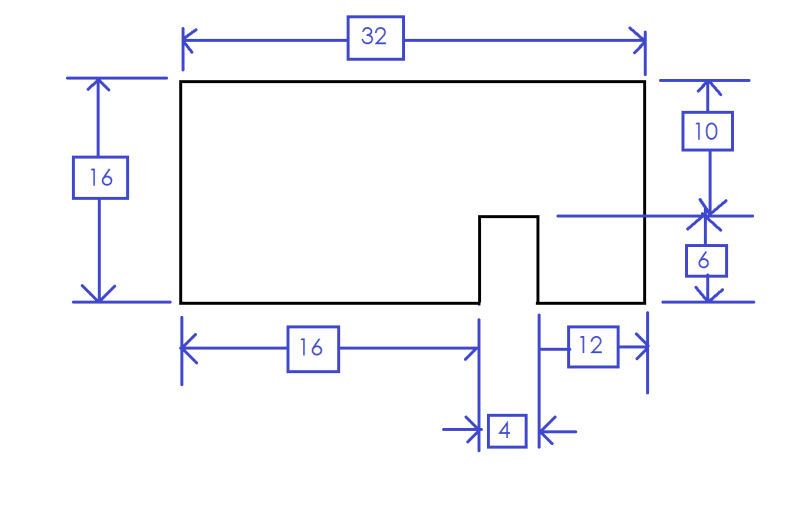
dwg_pk41ga.png


If this would be okay, how is rounding dealt with? What would happen if I decided to add another basic dimension for the overall diagonal, which would be the sqrt of 16^2 + 32^2 = 35.77708...?
It'd make my job a lot easier if prints were overdimensioned with basic dims rather than underdimensioned which is why I'm curious about this.
 
Replies continue below

Recommended for you

Would make YOUR job a lot easier if you take the basic dimension YOU need directly from the model (not from the print)
 
Imagine that this was hand drawn blueprint.
If you change a basic dimension on the bottom, what are the chances that you'll forget to change the top dimension?
(e.g. what if the 4mm slot became a 5mm slot...)

There should be a single definition for the basic shape of the part.
This prevents mistakes, like in my example, and helps to prevent double-dimensioning features (provides a single source of truth).

If it is desired to show a resultant dimension for clarity (for example, the 32mm dimension above), that dimension should be reference.
 
G_Apache,

I would say that this basic dimensioning scheme would be okay. There is no issue with adding more basic dimensions.

I'm not sure what to say about the issue of rounding - this will always be present, regardless of what type of dimensioning is used. One rule that Y14.5 does have is that the number of decimal places in the geometric tolerance value should match the number of decimal places in the applicable basic dimensions (for inch units, anyway).

Evan Janeshewski

Axymetrix Quality Engineering Inc.
 
Make dim's that are related to the datums as basic. Making all random dim's as basic is confusing.

Chris, CSWP
SolidWorks
ctophers home
 
Basic extra dimensions are simply redundant, but don't create the consequences of over defining by directly toleranced dimensions.
 
Underdimensioned = incomplete drawing. Same as not including the material for the part.

The matching rule for decimal places for inch dimensioning is just a way to see if the drafter is paying attention to the rule. It may have some value, and it isn't applied to metric dimensioning which has a different rule, but it often makes for a more crowded drawing than required.

In a CAD model all values have the same number of bits regardless of the displayed truncation. In some cases, where the CAD model is given as the source of information, every possible dimension can be noted/marked/defined as being BASIC, regardless of the number of places that would be required to display the value to the user.

It is a peculiarity of computing that fractional powers of 10 are repeating binary digits.

The number 0.1 can be represented in binary as 0.00011001100110011... . The pattern of 0011 repeats infinitely. We can't store the binary equivalent of decimal 0.1.
 
The matching rule for number of decimal places of BASIC inch dimensions vs. tolerance value specified in FCFs was abandoned in Y14.5-2009.
 
The rule for inch dimensioning still applies between the dimension and its directly applied tolerance. "1 +/- 0.0001" is not compliant for inch values, but is OK for the metric ones. Strange rule, but the CAD software usually takes care of it.
 
I agree that the rule stating that 1 +/-.0001 (dimension in inches) is incorrect is strange.
 
Status
Not open for further replies.

Part and Inventory Search

Sponsor