Continue to Site

Eng-Tips is the largest engineering community on the Internet

Intelligent Work Forums for Engineering Professionals

  • Congratulations waross on being selected by the Eng-Tips community for having the most helpful posts in the forums last week. Way to Go!

How to analyze a hollow core slab diaphragm?

Status
Not open for further replies.

nivoo_boss

Structural
Jul 15, 2021
130
Hey everyone!

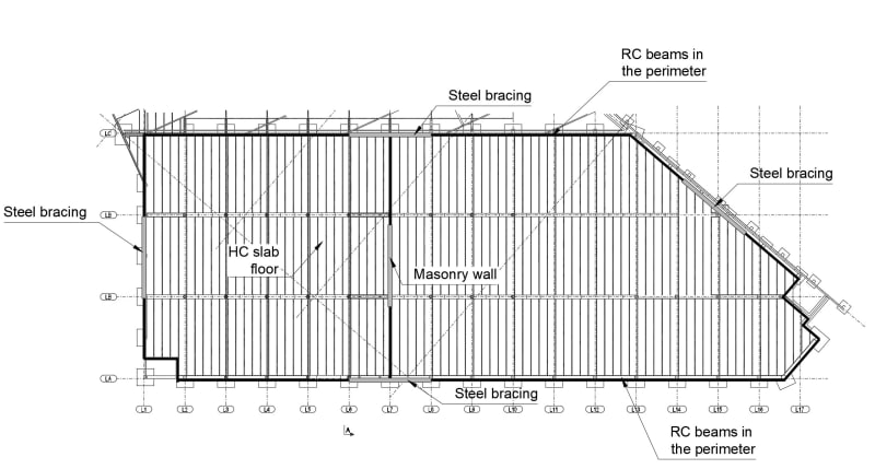
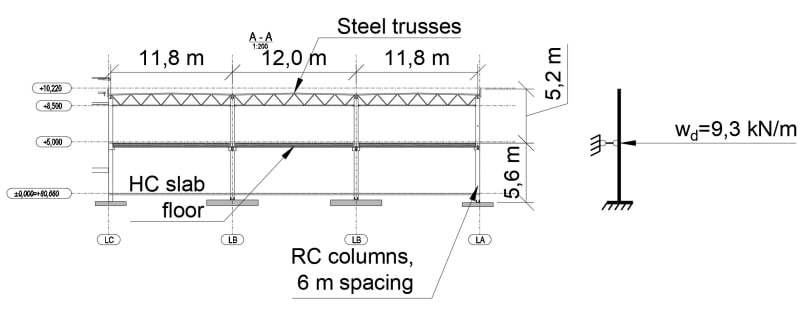
So I have this rather long (~100 m) two-storey building. It's supported by RC columns. The second floor is made up of RC beams and hollow core slabs. The roof has steel trusses. The columns are spaced 6 m and 12 m. It has a masonry wall running in the middle across the building.

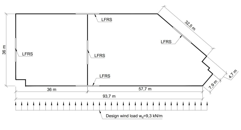
The plan is shaped like a trapezoid. I want to use the hollow core floor as a diaphragm to transfer the wind loads to the surrounding walls I marked on the plans. Perhaps you can give some advice on how to analyze this diaphragm reasonably? On the side and gable walls I would use steel bracings and in the middle there is a masonry wall. There is no seismic activity in my region.

1) A general plan of the diaphragm:
plan1_u9rrvi.jpg


2) A plan with the slabs, columns etc:
plan2_lsunaz.jpg


3) A section and a diagram. I would like to use this diagram to design the columns:
plan3_whr1bb.jpg
 
Replies continue below

Recommended for you

Do you have a continuous structural concrete topping that you can use? When used - it's typically a nominal 2 inch thickness. If so you have a pretty consistent load path for your diaphragm.

If not, which is the more cost-effective solution, the PCI Manual for the design of hollow core slabs has some guidance on diaphragm behavior. In my opinion, there are some elements in a hollow-core diaphragm which raises some questions. The grouted joint between hollow-core panels can reasonably shown to transfer shear loads - but any tensile loads through that joint will have to be resisted through grout bonding to hardened concrete in tension...

Some hollow-core manufacturers are able to provide imbedded steel plates in their hollow-core plank. If so - that also provides a consistent load path for your diaphragm loads.
 
There will be a fibre-reinforced concrete floor on top of the HC slabs (at least 100 mm thick).
 
At 4 inches you could design that topping to be your diaphragm. Chords and collectors might be able to be entirely located within that topping. Transfer of collector forces to your LFRS and the local transfer of cladding loads to your diaphragm may require you to combine your topping to your hollow core cores to ensure there is sufficient space and load paths to transfer those loads.
 
Okay, but would be the best way to model this topping? In software, I mean.
 
A 4" thick topping would act just like a rigid diaphragm. There's no way that would be considered even semi-rigid in a low/non seismic zone.

PCI has a hollowcore design manual which goes through diaphragm design in depth. Last I was googling, I found it relatively easily.

Edit: It's free direct from PCI, take a look at downloading it here

Generally speaking the hollowcore can act as it's own diaphragm due to the connection between adjacent panels just strictly due to joint grouting.

Let's not forget you have what may be the most structurally optimal layout of your lateral elements. The demand on this diaphragm looks tolerable. And with perimeter concrete beams acting as chord and transfer elements you're in good shape there.
 
Thanks for the link!

But let's say I want to evaluate the force distribution around the lateral supports. I'm thinking I'll model the columns with the bracings in a separate FEM model, apply some lateral load to it and calculate the system's stiffness. After that I would model a concrete plate in FEM, that's basically shaped as my first drawing, and I would place line supports at these places. The horizontal stiffness of the supports would be what I calculate from the separate models where I modeled the columns and bracings. I would apply a lateral load to this plate and check the results. How do you feel, would that give me reasonable estimates of the forces?
 
I think you need to try determining a non-fem solution first so you get an idea of the forces you're expecting at each. Otherwise you'd have no idea whether the software output is correct or not. With a non-complicated layout like yours, the hand calcs on this diaphragm and determining the forces in the braces should be quite simple.

What program are you trying to analyze in? It won't let you model the slab in conjunction with the steel framing?
 
With a rigid diaphragm the forces will go to where the stiffness is. In this situation that is a close enough approximation to reality to be able to design for.
 
Status
Not open for further replies.

Part and Inventory Search

Sponsor