Eng-Tips is the largest engineering community on the Internet

Intelligent Work Forums for Engineering Professionals

How to Get Emergency Diesel Generator Started automatically? 1

Status
Not open for further replies.

Histor

Electrical
Mar 2, 2022
70
0
0
SG
Hi,
Please help me to understand on how to wire emergency diesel generator to Switchgear so that when there's a power failure, Generator can start automatically.
I am clear about power cabling. I'm confused about the control cable wiring. I need to sense the voltage loss in Switchgear so that the generator will start and feed to emergency control panel.

Generator_aoi2md.png


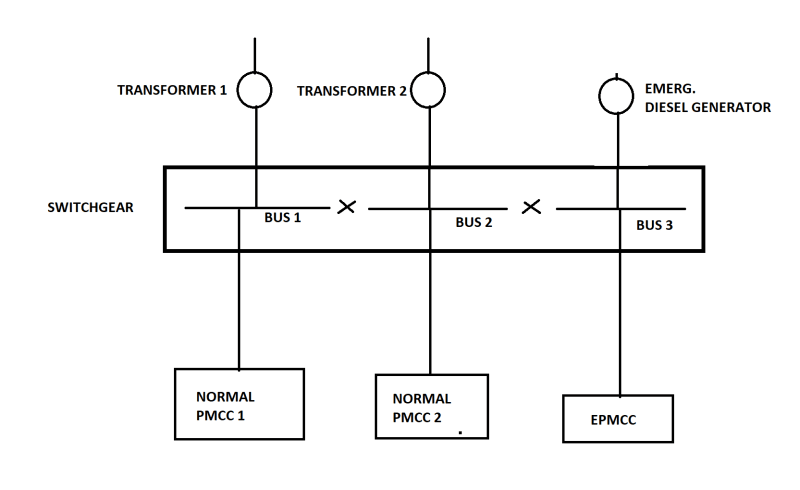
I want Generator to start automatically when there's a power loss in switchgear.

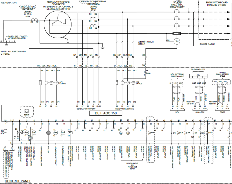
Below is the generator vendor wiring. Please help me understand how can I do control wiring to get generator automatically start.
Generator1_f1wks2.png
 
Replies continue below

Recommended for you

Your diagram doesn't show how the emergency diesel generator interacts with the busses.

This resembles a marine application. Typically there is a bus tie breaker between bus 2 and bus 3. This breaker has an under voltage cutout so it opens when the bus voltage falls below a certain level. This islands the emergency bus. Upon loss of voltage to the emergency bus the emergency diesel generator will start and connect to the emergency bus. The bus tie breaker will remain open.
 
Dear Mr Histor (Electrical)(OP)15 Mar 23 03:19
[COLOR=]"....Please help me to understand on how to wire emergency diesel generator to Switchgear so that when there's a power failure, Generator can start automatically....."[/color]
1. It shows that the interlocking is by [incoming breaker and the tie breaker] with "two out of three" formation.
2. Attention, your drawing omitted that there shall be a Trafo 1 incoming breaker, Trafo 2 incoming breaker and DG incoming breaker respectively.
3. Monitor the voltage on Bus 1 and Bus 2 respectively. DG starts up automatically when either Bus 1 or Bus 2 voltage failure.
4. Proposal, add a new DG Tie breaker connecting Bus 3 to Bus 1.
Note: This new DG Tie breaker may by rated based on the DG kVA rating; which is likely to be lower than Trafo 1 or Trafo 2. kVA rating.
5. When power from Trafo 1 failed, DG starts up and feed power From Bus 3 to Bus 1 through this (additional new) DG Tie breaker.
Note: When Bus 2 failed, DG starts and feeding Bus 3 to Bus 2 through the existing Tie breaker.
Che Kuan Yau (Singapore)
 
You can't have the generator permanently connected to the bus.
Order a generator with automatic start function.
This function typically wants a contact closure across two terminals.
The generator will start and run as long as this circuit is closed.
If your generator does not have this function, order an automatic start module from the supplier.
Buy a suitable Automatic Transfer Switch. (ATS)
The ATS will have a pair of "Generator Start" terminals. Connect these terminals to the start terminals on the automatic start module.

Plan "B".
If you add a breaker for the generator, rather than using an ATS:
The generator breaker MUST BE interlocked with the breaker between bus 2 and bus 3.
Additionally, there must be at least two independent interlocks.
It is not a case of IF the interlock fails, it is a case of WHEN the interlock fails.

You will need another circuit.
Use a phase and voltage monitoring relay connected at the generator breaker[sup]1[/sup] to detect proper voltage and phase sequence from the generator.
Use this information to close the generator voltage.
When the power returns, a third circuit opens the generator breaker and after a suitable delay[sup]2[/sup] closes the bus 2/ bus 3 breaker.
Then, after a second delay, the generator is stopped.[sup]3[/sup]
These functions are implemented in an ATS.

1: This must be connected at the breaker rather than the generator to detect phase reversal in the event of a wiring error during maintenance work.
2: Large motors may be damaged by an out of phase transfer. It is good practice to allow enough time for the back EMF to decay in the large motors before closing the line breaker.

3: This is the cool down time. It is good practice to run the engine unloaded for about 5 minutes to allow the turbo to cool down and spool down before stopping the engine (and stopping the oil flow to the turbo bearings).

--------------------
Ohm's law
Not just a good idea;
It's the LAW!
 
waross, in this case as IRstuff as alluded to, the Deif will likely handle mains failure, and can be configured to auto-start on loss of mains.

However, as you note, it either needs a separate ATS, or the Deif needs to monitor the appropriate bus and either trip the mains breakers or the mains breakers need to be fitted with their own UV elements.
The drawing indicated, if my memory of Deif terminals is correct, has no input for the mains volts monitoring (marked as ML1, ML2, ML3 with nothing connected to it). I also note that Deif has a number of AGC 150 models so this may be one of the lesser capable units.

The catch with this configuration is the mains detection in this type of controller normally has the load in between the gen breaker and the mains breaker, in much the same way as the Deif picture below.
For this context then mains monitoring would ideally be done on the Bus 2 side of the Bus Tie, with a UV element automatically opening the bus tie upon mains failure. Such an arrangement would prevent bumpless transfer back to mains though. This arrangement also prevents powering the normal MCCs from the generator as otherwise the mains monitoring will falsely detect mains if the bus is closed and powered by the generator.

There are implications as to where the voltage monitoring is connected and how the system functions, so it's worth taking a step back and ensuring that the functionality is as expected. Is this a marine application for an emergency bus as Tug guessed?

AGC150_ngt5yq.jpg


N.B. It is great to have you back waross.

EDMS Australia
 
Thanks Freddy.
I guess that I should have looked up the AGC 150.

You mentioned "Bumpless transfer".
That may cause issues.
I installed a number of sets with very fast, open-transition transfer switches.
The switches were so fast that they had to be in-phase before transferring back to the mains.
One issue was the sped of transfer and the possible effect on motors of such a fast out-of-phase transfer.
A second issue was the extremely close spacing of the main contacts.
An out-of-phase transfer could easily result in a flash-over of the main contacts.
BUT,
It may take 20 minutes or more for the phase angles to drift into alignment.
I had customer complaints about extended running on the generator when the mains were available.
And thanks for the welcome back.


--------------------
Ohm's law
Not just a good idea;
It's the LAW!
 
Bumpless transfer probably isn't the best term for what I'm referring to. The Deif units (I'm familiar with the older GPC series rather than the newer AGC150) are mostly capable of synchronising, hence the use of bumpless transfer. Fast Open-Transition as you note may cause issues.


EDMS Australia
 
Are the Deif units capable of nudging the speed?
The very fast open transition switches had sync check.
The problem was when the frequency matched the line frequency but was out of phase.
It could take a long time to drift into sync.
The problem with very fast transition was before transition, not during or after transition.

--------------------
Ohm's law
Not just a good idea;
It's the LAW!
 
They normally have a speed bias output in one form or another (CAN, 4-20mA, 0-5V etc) that will interface with whatever's on the engine, to be able to synchronise, and parallel load share with other similar connected units. There's obviously a minimum threshold for capability and in all my applications they've had it, lower spec mains fail non-synchronising units might not but I've never had a reason to look.

EDMS Australia
 
Status
Not open for further replies.
Back
Top