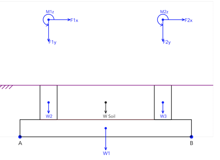
I am designing a Combined foundation with 2 pedestals P1 & P2.

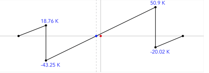
I am trying to draw the Shear and Moment Diagram and still confused about the vertical forces how to include it in the Shear diagram.
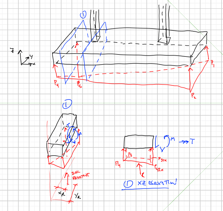
Pressure under Foundation is p1, p2, p3 & p4.

Volume of pressures under Footing = (p1 + p2 + p3 + p4) / 4 * Length Foundation x Width Foundation
if Fx1 & Fx2 = 0 or Fx1 + Fx2 = 0 then Fy1 + Fy2 = Volume of pressures under Footing.
I can draw properly the Shear Diagram only if Fy1 + Fy2 = Volume of pressures under Footing.

if Fx1 & Fx2, then the values of p1 + p2 + p3 + p4 will be changed and then the volume of pressures under foundation will be changed.
if so, I won't have Fy1 + Fy2 = volume of pressures under foundation
Please help, I stuck for months with this trying to draw shear diagram when ever Fx, Fy and Fz exist.
I search all book and you tubes trying to find a combined foundation examples with biaxial moment and forces and found nothing.

I am trying to draw the Shear and Moment Diagram and still confused about the vertical forces how to include it in the Shear diagram.
Pressure under Foundation is p1, p2, p3 & p4.

Volume of pressures under Footing = (p1 + p2 + p3 + p4) / 4 * Length Foundation x Width Foundation
if Fx1 & Fx2 = 0 or Fx1 + Fx2 = 0 then Fy1 + Fy2 = Volume of pressures under Footing.
I can draw properly the Shear Diagram only if Fy1 + Fy2 = Volume of pressures under Footing.

if Fx1 & Fx2, then the values of p1 + p2 + p3 + p4 will be changed and then the volume of pressures under foundation will be changed.
if so, I won't have Fy1 + Fy2 = volume of pressures under foundation
Please help, I stuck for months with this trying to draw shear diagram when ever Fx, Fy and Fz exist.
I search all book and you tubes trying to find a combined foundation examples with biaxial moment and forces and found nothing.

