Continue to Site

Eng-Tips is the largest engineering community on the Internet

Intelligent Work Forums for Engineering Professionals

  • Congratulations KootK on being selected by the Eng-Tips community for having the most helpful posts in the forums last week. Way to Go!

Extent of negative moment reinforcement

Status
Not open for further replies.

tmalik3156

Structural
Jun 21, 2021
97
Good day.
Suppose we have a multi-span continuous bridge deck. We need to provide negative steel to the deck on both sides of the pier. The question is how far from the pier should we terminate the negative steel?

1. Draw dead + superdead load moment diagram. Terminate negative steel at the point of contraflexure.
2. Same as 1 but extend a little more to include development length.
3. Use dead + superdead + live load moment diagram, and terminate at the point of contraflexure (or extend to include development length)

Can someone please provide me a reference (Code) on what is the correct method? I have heard from other people, but I need solid reference.

Personally, I would go with 2., but I cannot explain it properly.
Also, if you follow a thumb rule, please share.
Thank you
 
Replies continue below

Recommended for you

Per AASHTO, an area of reinforcing equal to 2/3 of 1% of the deck cross-sectional area must extend beyond the point where the tensile stress in the concrete is less than 0.9fr (90% of the rupture stress). In lieu of calculating the stress, we have extended the required steel a distance equal to 25% of the length of the longer span on each side of the pier.
 
and try not to terminate the bars at one location... staggering them helps a tad...

-----*****-----
So strange to see the singularity approaching while the entire planet is rapidly turning into a hellscape. -John Coates

-Dik
 
Assuming you have steel girders, AASHTO LRFD 6.10.1.7. However, I like BridgeSmith's approach better.

Our DOT stagger every other rebar 3' longitudinally.
 
Most codes require the reinforcement to be extended between D and 2D past the point of where it is required for flexure plus development, or the calculation of a longitudinal tension force from shear that must be added to the flexural tension requirements. So at the point of contraflexure, the area required D to 2D back from that point has to be provided and developed past that point.
 
If you're going by the calculated 0.9fr, yes, the bars would need to be developed beyond that point.

We have never staggered the ends of the bars, but we don't terminate them at the end of the section, either; they're lapped with #4 bars that extend through the positive moment regions.

For an integral abutment, the #4 bars get lapped with #6 bars at the 1/4 point of the end spans, and those run to the abutment and get bent into the end diaphragm.
 
lapping helps... no abrupt termination at one point.

-----*****-----
So strange to see the singularity approaching while the entire planet is rapidly turning into a hellscape. -John Coates

-Dik
 
Our DOT runs #4's in the top mat longitudinally for the entire length of the deck, then adds a #6 in between the #4 for negative moment steel.
 
Thank you all for your replies. They are helpful.

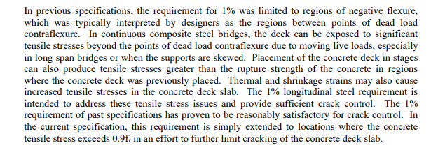
Steel Bridge Design Handbook Chapter 17 seems to indicate that it was a past practice to define negative moment region by the points of dead load contraflexure. It is relatively easy to find this distance from the piers.

Then the handbook goes on to talk about the tensile cracking requirements.

Screenshot_2023-03-29_190936_isntaa.png


It is however, difficult to determine exactly up to what length from the pier the tensile stress in deck exceeds the factored tensile strength. So approximations like 25% mentioned by Bridgesmith is helpful, though it is not per the code.

Bridge decks have typically 10 mm of waterproofing layer. So, in my opinion even if there are some cracks developed beyond the point of dead load contraflexure, they are not that harmful. So I will go with Option 2 I mentioned in the original post.
 
It is however, difficult to determine exactly up to what length from the pier the tensile stress in deck exceeds the factored tensile strength.

We haven't found it to be that difficult. It's just M/S. Calculate S for the composite section with the deck transformed to an equivalent area of steel (divide by the modular ratio, n), divide the max moment at 10 or 20 points along the span by S to get the stress, and transform the concrete back (multiply by n). Easy peasy with a girder line analysis program and Excel.
 
Bridge decks have typically 10 mm of waterproofing layer.

They do? Ours typically don't unless it's needed, which usually isn't until 20 years or more into its service life.
 
@ BridgeSmith, Thank you.

Typically we don't do calculations for deck steel. Empirical method, which takes into account the arching action of the slab, indicates that we could provide 15M @ 300 mm the entire length of the deck, and then only in the "negative moment regions" we need to add 20M @ 300 mm alternating with those 15Ms. This gives the 1% steel required. This is similar to what 3Fan above was referring to. But then the question comes, how far does this "negative moment region" extend? If we use live loads (in addition to dead loads), then it becomes computationally difficult because - depending on the position of the vehicle - we could see the presence of the negative moment far away from the piers. Then we would end up providing "negative" steel nearly the whole length of the bridge save near the abutments! That's why defining "negative moment region" in terms of dead load contraflexure only is perhaps more reasonable.

Frequent use of de-icing salts from late November to early April, and the freeze-thaw cycles of penetrated water makes it mandatory for bridge decks to have 10 mm waterproofing.
 
Per AASHTO, 2/3 of the required 1% steel must be in the top layer and must extend a development length beyond the point where the tensile stress in the concrete due to the Service II load combination is less than 0.9*fr (See AASHTO LRFD 6.10.1.7). Depending on the DL to LL ratio, this may be more or less than the DL contraflexure point, but we've always found it to be less than 25% of the longer span adjacent to the pier under consideration.
 
@ BridgeSmith
Yes, I understand that it is the tensile stress in concrete that we are talking about. The mention of waterproofing came because even if there is some tensile crack in concrete deck, it is covered by the waterproofing layer - so salt and water cannot penetrate.

CHBDC design philosophy is similar to AASHTO. But of course,the load factors and resistance factors of SLS1 are different from AASHTO Service II.

Screenshot_2023-03-30_105844_wyrogo.png
 
Of course if you have a waterproofing layer (epoxy overlay?), then deck cracking would theoretically be less detrimental. However, if you're designing per the spec, then the provision would apply regardless of what you add to waterproof it.

FYI, the Service II load combination factors component DL by 1.25, wearing surface DL by 1.5, and LL by 1.3.
 
Thanks. CHBDC SLS1 has the following load factors.
DL = 1.0
LL = 0.9

But the resistance factor phi = 0.75

Waterproofing material is rubberized asphalt, plus fibre board and special fabric.
 
Waterproofing material is rubberized asphalt, plus fibre board and special fabric.

Interesting. And this is the 10mm thick overlay that goes on the bridge deck?
 
Yes, it's something like the one shown in the video:
Waterproofing consists of two layers of rubberized asphalt, a fabric reinforcement (white sheet) and a protection board. All together make 10 mm.
The fabric reinforcement adds an extra impermeable layer. The protection board protects the waterproofing from getting melted and dislodged when hot asphalt (wearing surface) is placed on them.

 
Ah, so it's a water proofing membrane that gets covered by an asphalt overlay? That makes more sense. We've been using a fabric membrane for that, and have just started using a liquid membrane that I think is similar. However, most of our bridge decks don't get asphalt overlays; they're bare concrete until 15 to 40 years later, when we add an epoxy (3/8") or concrete (1 1/2") overlay.
 
@tmalik3156
My thought would be 3 + past the inflection point would apply? Is there any reason why we wouldn't at least consider LL in your negative moment envelope?

This is from the CHBDC. The Concrete Design Handbook has Figure N12.12 describing the clause.
Capture_mixay8.png


You would also need to check a particular section for minimum (and maximum) reinforcement per Clause 10.11.5.3.2 as you indicated and reinforcement ratio and cracking moment. The 2014 CHBDC used to also require you to check the crack width associated with your reinforcement, with 0.25 mm being the max crack width for a bridge deck subject to de-icing chemical. In 2019 they have changed it to a stress based check.
Capture_g7wfrz.png


@BridgeSmith
Bridge deck in Canada are almost always exposed to de-icing chemical. We rarely have bare concrete decks.
 
Status
Not open for further replies.

Part and Inventory Search

Sponsor