Continue to Site

Eng-Tips is the largest engineering community on the Internet

Intelligent Work Forums for Engineering Professionals

  • Congratulations waross on being selected by the Eng-Tips community for having the most helpful posts in the forums last week. Way to Go!

Rigid element - FEMAP

Status
Not open for further replies.

Cathie16

Materials
Mar 30, 2023
11
Hello all, I am new here and started working with Femap since 2 months. I am currently analyzing a pressure vessel which is connected to the flange through a nozzle. Since it is a standard flange I dont model flange but apply only the load (imposed by the weight of flange - nozzle loads in asme) on the surface that connects the nozzle and flange using rigid element (spider nodes). But we find the maximum allowable stress is just over a limit on this surface (by stress linearization) and we think it might be due to the rigid element. If flange is modeled it might control this effect to a certain level? And hence I want to add some flexibility to these spider nodes to have freedom of movement in only certain direction. Is it possible to do that? Or should I model the Flange itself?

Thanks in advance for your help and time.
 
Replies continue below

Recommended for you

Dear Cathie,
This is a complicated answer, rigid RBE2/RBE3 elements is a way to transmit load & displacements effect without the need to mesh in detail a component, in your case the flange, but if you have critical local effects then the use of rigid elements is questionable. Please note:
RBE2 is all rigid: your flange is ininitely regid?. The anwer is not at all, then you have a point. The RBE2 element uses constraint equations to couple the motion of the dependent degrees of freedom to the motion of the independent degrees of freedom. Consequently, RBE2 elements do not contribute directly to the stiffness matrix of the structure and ill-conditioning is avoided. The RBE2 provides a very convenient tool for rigidly connecting the same components of several grid points together, but is devasting.
RBE3 instead is a way to transmit remote loads or remote mass, do not add any stiffness to the structure, it simply translate loads the same way you do if transmiting loads "manually". But in this case using RBE3 you ignore the stiffness of the flange.

Then, in all cases you pay a price: in real life nothing is completrly rigid o flexible, we have levels ... Consider meshing the flange & bolts to capture local stiffness and compare results.
To learn more about rigid elements with Simcenter FEMAP & NASTRAN you can visit my blog:

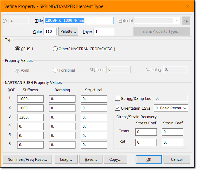
And consider the use of CBUSH 2-nodes elements as well, you can control stiffness in any direction:
cbush_lhid5f.png


Best regards,
Blas.

~~~~~~~~~~~~~~~~~~~~~~
Blas Molero Hidalgo
Ingeniero Industrial
Director

IBERISA
48004 BILBAO (SPAIN)
WEB: Blog de FEMAP & NX Nastran:
 
Thanks a lot for your reply. I checked out your blog, unfortunately its in a language I dont understand. And google doesnt translate everything neither. But still I understand the concept to some extent. Thanks again!
 
Dear Cathie,
You have GOOGLE TRANSLATE to use it at your needs, here you have the command:

And the result:

Best regards,
Blas.

~~~~~~~~~~~~~~~~~~~~~~
Blas Molero Hidalgo
Ingeniero Industrial
Director

IBERISA
48004 BILBAO (SPAIN)
WEB: Blog de FEMAP & NX Nastran:
 
Status
Not open for further replies.

Part and Inventory Search

Sponsor