Hello everybody,
I'm running into a cooling problem at work on our UAV, essentially the engine is running too hot and I've been tasked to find a solution.
At the moment we have an automotive configuration with the radiator in front of the aircraft and an axial fan right behind the radiator that sucks air in (pull configuration). The fan actually cover only 1/3 of the radiator area and it's basically attached to the back of the radiator with very little gap.
The cooling issue happens when we are on the ground with the fan at max speed, there is simply not enough air going through. We do not expect any cooling issue when in forward flight (fan turned off) since we're gonna have plenty of ram air being pushed through the radiator.
Basically my points are:
- Use two fans instead of one (this alone is not enough though)
- Air flow distribution through the radiator should be as uniform as possible, to achieve it:
- Use some sort of plenum that cover the entire radiator and direct the air to the fans intake.
- The fans should be located as far as possible form the radiator.
- Use guidevanes to compensate for sharp bends (actually used in the past and they work great).
- Redesign the radiator to get a lower pressure drop on the air side.
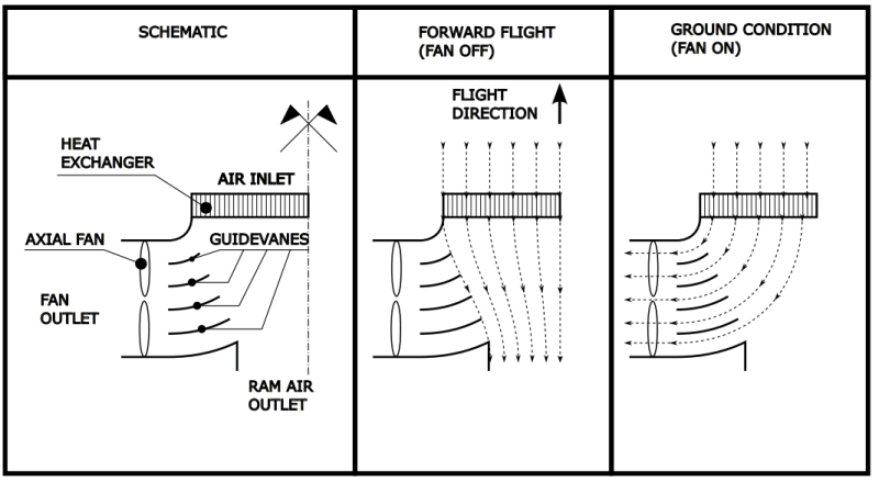
An additional feature I'd like to implement is to differentiate the air paths when the aircraft is on ground with the fans on and when the aircraft is in forward flight with the fans off. This is both to avoid the fans windmilling during forward flight and to avoid the additional drag from the same fans.
My idea on how to solve this is schematically shown here below.
In the figure is shown the top view of the aircraft, only half of the UAV is shown since it's symmetrical.

My doubt is if something like this would work, especially the point about the two different air paths. The easiest thing would be to put a louver system that close or open the path to the fans but I cannot add any additional weight/actuator so I came out with this "fluid dynamic" solution instead of a mechanical one.
Before starting doing CFD/prototypes I'd like to know your opinion or if you had/know any similar situation. Is the airflow I indicate in the picture realistic for the ground/flight situation?
To summarize my (wishful) thinking is:
- during forward flight no air should go through the fans outlet.
- during ground operation no air should be sucked from the ram air outlet port.
Thanks in advance.
I'm running into a cooling problem at work on our UAV, essentially the engine is running too hot and I've been tasked to find a solution.
At the moment we have an automotive configuration with the radiator in front of the aircraft and an axial fan right behind the radiator that sucks air in (pull configuration). The fan actually cover only 1/3 of the radiator area and it's basically attached to the back of the radiator with very little gap.
The cooling issue happens when we are on the ground with the fan at max speed, there is simply not enough air going through. We do not expect any cooling issue when in forward flight (fan turned off) since we're gonna have plenty of ram air being pushed through the radiator.
Basically my points are:
- Use two fans instead of one (this alone is not enough though)
- Air flow distribution through the radiator should be as uniform as possible, to achieve it:
- Use some sort of plenum that cover the entire radiator and direct the air to the fans intake.
- The fans should be located as far as possible form the radiator.
- Use guidevanes to compensate for sharp bends (actually used in the past and they work great).
- Redesign the radiator to get a lower pressure drop on the air side.
An additional feature I'd like to implement is to differentiate the air paths when the aircraft is on ground with the fans on and when the aircraft is in forward flight with the fans off. This is both to avoid the fans windmilling during forward flight and to avoid the additional drag from the same fans.
My idea on how to solve this is schematically shown here below.
In the figure is shown the top view of the aircraft, only half of the UAV is shown since it's symmetrical.

My doubt is if something like this would work, especially the point about the two different air paths. The easiest thing would be to put a louver system that close or open the path to the fans but I cannot add any additional weight/actuator so I came out with this "fluid dynamic" solution instead of a mechanical one.
Before starting doing CFD/prototypes I'd like to know your opinion or if you had/know any similar situation. Is the airflow I indicate in the picture realistic for the ground/flight situation?
To summarize my (wishful) thinking is:
- during forward flight no air should go through the fans outlet.
- during ground operation no air should be sucked from the ram air outlet port.
Thanks in advance.
