Continue to Site

Eng-Tips is the largest engineering community on the Internet

Intelligent Work Forums for Engineering Professionals

  • Congratulations waross on being selected by the Eng-Tips community for having the most helpful posts in the forums last week. Way to Go!

Thoughts on unusual beam-beam connection - original bottom flange to new top flange 2

Status
Not open for further replies.
Apr 29, 2023
31
GB
Hello Folks,

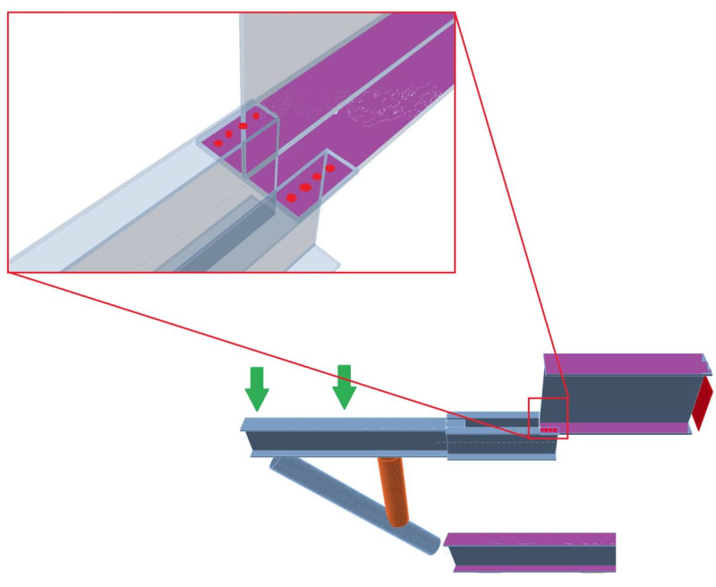
I was wondering what your general thoughts might be on an unusual connection that I've been asked to assess. I've attached an image and can clarify if anything is unclear. The section I am considering is a 20 year old extension to 50 year old structure. The extension consists of a propped beam/truss supporting vertical and horizontal loads.

The internal connections joining the members of the truss extension together are pretty standard but the connections joining the extension to the original steel (purple flanges in image) are unusual as they are an after-thought that have to fit around other elements. The bottom prop connection has an eccentric work point which seems unnecessary to me but is not as unusual as the hanger connection.

The top beam/cantilever has channel extensions to fit around existing objects before meeting the original steel. The hanger connection to the original steel consists of 4 no. bolts with no stiffners, blacking plates or additional support so it's not a full moment connection but I am wondering if it should be considered pinned or partially rigid. The rigidity of the connection will obviously effect how much it will be loaded so I don't think just assuming it as either pin or full moment connection is particularly useful.

I'm also unsure what the critical failure modes might be as there is a lack of guidance on similar connections in any literature I've read. Presumably the lack of similar connections is because it's not a great design, which is clear from first glance. I've been looking a yield line analysis guidance in AISC DG04 as I thought the unstiffened column flange yield line pattern in table 3.4 might be similar but I could be widely off base with that as I don't have significant experience in steel connection design.

Beyond that potential failure mode, I was also wondering if considering the connection as a t-stub in tension might be more valid (such as I looked at eqn J10.1 of AISC 360-10 for local flange bending but I think that might only be suitable for single point loads rather than a series of point loads in a bolt group. There may be an applicable section of AISC 360 that I have missed.

Any thoughts or opinions on failure modes or how best to model the connection are welcome. Thanks in advance.
 
Replies continue below

Recommended for you

If the assembly works when a pin is assumed, then assume a pin. If the assembly relies on a moment capacity at that connection, then provide remedial measures to ensure that statics can be satisfied.
 
The top beam connection is going to see mostly an axial tension load. Ensure the bolted joint can take the tension load. Critical failure mode might be net section in the channels, bearing in either part, or fastener shear.

What does the bottom connection look like in detail? Can it take all of the vertical shear + axial compression?

20 years after this was built, you now need to assess it? Why?
 
Thanks for the responses.

BAretired, I hesitated to go straight to assuming the connection as a pin as the change in stiffness will obviously how change the load is distributed to the original primary steel and if the connection does carry non-negligible moments then I would expect that to decrease the bolt tension capacity available for the maximum allowable vertical load. I was hoping to attempt an approximation of the realistic behaviour of the partially rigid connection but that may not be an achievable goal if the consensus is to ignore any rigidity in the connection.

"Critical failure mode might be net section in the channels, bearing in either part, or fastener shear."

SWComposites, Thanks. I have considered those modes, I just wanted to make sure I was not missing anything like prying action or local effects from additional bolt tension due to moment.
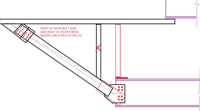
I've attached a quick sketch of the bottom connection, I believe it is acceptable as I understand the stiffness, strength and failure modes of the connection more completely than the top connection as there is more guidance available.
It's in an industrial setting and the new owner has different operational needs than the previous one and so they original analysis and design is not useful for this scenario. They want to increase the load on the structure by a factor of 3 of the original design spec and would like to know how realistic that goal is. It's not realistic at all and there are alternative solutions but I would still like to determine a safe maximum weight.
 
 https://files.engineering.com/getfile.aspx?folder=4ebf215a-ad55-45c7-b447-2cfeb1a9bf4e&file=Truss_BottomConnection.png
Well, I don’t like the looks of the upper connection; it appears to be prone to a two part fracture thru the fastener holes. There probably is some minor prying on the fasteners, so I would ensure the fastener heads and nuts are large. Make some conservative assumptions for that joint, and have some extra capability, and if that isn’t sufficient for the increased load, then just say “No”.
 
Definitely a no from me. I would be worried about shear. What is the shear failure plane?
 
SWComposites, thanks again. From your and others comments, I think that my idea to follow AISC DG04 unstiffened column flange yield line pattern may not be appropriate. I may look into how prying action/force changes due to assumed connection stiffness : pinned vs semi-rigid (based on moment of inertia of the bolt pattern) vs full moment (unrealistic I know but may include for completeness).

rapt, I'm sorry but I'm not 100% sure what shear failure plane you are referring to? If you mean bolt shear: it is a single lap joint (610x305 channel top flange straight to 1200x500 PG bottom flange) with a single shear plane assuming threads in shear. If you are referring to block shear failure plane: I believe it would be similar to the following image ( Apologies if I have misunderstood.

Both, I don't disagree with your approach and saying "no" to an unrealistic goal weight is reasonable and sensible but if possible I would still like to achieve the study's secondary objective of estimating maximum allowable weight, regardless of how near or far it is for the goal weight.
 
Both connections seem "unideal" to me and probably could have been done in a better way. However unideal is what we engineers have to deal with a fair bit of the time.

Like most engineering problems whether the connections are suitable really depends on the magnitude of the loads.

The bottom connection looks like the critical issues could be buckling of the plate in axial compression or potentially even block shear of the top four bolts due to the eccentric loading. But I'd expect the former to dominate unless the plate was extremely thick.

The top connection is hard to guess at by inspection as it really depends. The connection clearly won't achieve anywhere close to the tensile capacity of the member. However I would presume that the member isn't sized according to its tensile capacity.

When it comes to odd connections you really need to find suitable means of analysis with the tools and skills you have available to you and to dedicate the time commensurate with the task. I generally try to approximate it to an existing connection that has documented checks. I have decent FEA tools at my finger tips so I'll also not hesitate to use that.
 
agree with rapt ... where's the shear loadpath (out of the diagonal brace) ?

and OP you talk about many detail issues (prying, etc). I don't think anyone is looking into that much detail, which of course need to be considered in the final analysis.

I'm looking at both the pix (virtually identical ?) and the only loadpath for shear (for the applied vertical loads) is the lower beam web ... the lower beam is in bending ... not Wrong, but not good.
Unless you add a diagonal truss on the RH of your pix.

as donkey (from Shrek) might say .... "ugglyyyy".

"Hoffen wir mal, dass alles gut geht !"
General Paulus, Nov 1942, outside Stalingrad after the launch of Operation Uranus.
 
human909: Thanks for the suggestions. I've considered those failure modes for the bottom connection as I am comfortable with that connection. I did attempt to identify approximate existing connections for the top connection such the unstiffened column flange yield line pattern and hanger t-stub prying action I suggested in earlier posts. One of the motivations to create the post was the possibility of others either confirming/rejecting these approximations or suggesting alternatives/additional literature. I do not have FEA solutions available that are suitable for connection level modelling unfortunately.

rb1957: Yes, the shear loadpath is out the diagonal brace to the lower 1200x500 plate girder. The reason why I am focusing on the top connection strength and stiffness is because that is where my uncertainty lies. I have no issues with the global analysis or the other connections and so they are not the focus of the post.
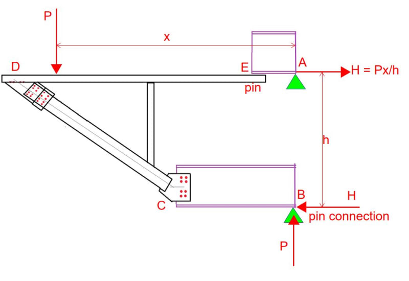
The second picture differs from the first as it includes a rough sketch of the bottom connection due to SWComposites asking "What does the bottom connection look like in detail?". I did not include it in the first picture because I am not uncertain about that connection. The study is to determine the current maximum allowable load so while the addition of supports would be beneficial, it's beyond the scope of work.
 
The boundary conditions need to be shown. I assume pin supports at points A and B. The connection at point C is much stiffer than the one at E, so the assumption of a pin at point E is not overly conservative. Connection C is required to carry the eccentric reactions at point B.

Capture01_mv5l8b.jpg


Capture02_concrn.jpg
 
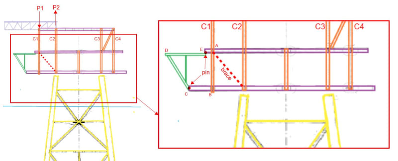
BAretired, Apologies for the lack of clarity for the boundary conditions. In your diagram A and B should be considered as continuous members. I might be too close to the project and had not realized vague references to primary steelwork would be less than helpful. The truss is an minor extension to a larger structure and the purple beams in the above images are part of that primary structure. I had assumed they would be seen as fixed in the above simplified images, which is poor communication in hindsight. I have created and attached a new image that hopefully clarifies how the extension (in green) relates to the rest of the structure (purple, orange, and yellow). That said, the focus of the post is the connection initially discussed rather than the behaviour of the truss in general and while I appreciate the willingness to offer assistance on other aspects, I don't want to trouble others with things that I am already comfortable with.

As a side note, I've also been using Paint to create the images, are there other software solutions more suited to diagram creation?
 
 https://files.engineering.com/getfile.aspx?folder=ec36fcc9-9567-4e83-9742-e791e8c120ad&file=OverallStructure.png
As an aircraft stress guy, I still don't like that upper connection at BA's point E.

OWS - was is the applied tension load at that connection, and what do you calculate for the total tension capability for the various failure modes: net section, bearing, fastener shear, etc. You should be able to do all that with hand calcs, no FEM required or necessary. If it was me, for any increase in loading, I would insist on that upper connection be redesigned, unless you have huge margins for the loadings.
 
man, BA is putting in a tonne of work to help you ... much better than drawing in "paint". IMO, anything, even pencil and paper is better than "paint" !

BA has detailed the structure very well, but I don't like member BC, I think the internal loads at C are quite problematical.

If CD is an axial loaded member (as it looks to be), then BC is (as drawn) a 2 force member ... but the forces don't look to be co-linear.
Therefore I see a moment at B, equal to the load in BC times the offset to the mid-depth of the beam at B,
which is a consequence of the lower beam web carrying the vertical component of CD.

"Hoffen wir mal, dass alles gut geht !"
General Paulus, Nov 1942, outside Stalingrad after the launch of Operation Uranus.
 
Sketch edited only to add reference points A, B, C, D, E.

Capture04_jxlggt.jpg


Okay, it's even better than I assumed before. You've got a diagonal brace between columns C3 and C4. That's okay, but I suggest a brace between C1 and C2 as well (dashed red line). If the roof truss is attached to both C1 and C2, there will be a substantial moment caused by forces P1 and P2, not to mention the moment caused by the green structure.

Analyze the structure as if there were pins as shown on the blowup drawing. Peace of cake! The bottom cantilever carries the vertical reaction from the lower pin. The bolts forming the upper pin are stressed in shear. Any vertical reaction is minor and may be ignored.
 
OffshoreWindStructures said:
As a side note, I've also been using Paint to create the images, are there other software solutions more suited to diagram creation?

There are probably many good graphics packages. I have tried a few, and have settled on PDF-Xchange Editor. That is the one I used here. PDF Annotator is also pretty good.
 
Something like:

Clipboard01_l9v51f.jpg


-----*****-----
So strange to see the singularity approaching while the entire planet is rapidly turning into a hellscape. -John Coates

-Dik
 
dik,

That would have been better, but it's been there for twenty years, so is it really necessary?
 
SWComposites: I agree with the concern for that connection, and I have looked at the typical failure modes via hand calcs already. I posted this question incase there might be an non-obvious failure mode I missed. Your suggestions are appreciated.

rb1957: if you are referring to the images BA has shared, I believe he is annotating images that I had previously created/altered in Paint (and statica) and shared in earlier posts. I am new to the forum and have not yet figured out how to embed images in a post rather than attach as a file. If these images are much better than drawing in Paint by itself then Paint and a pdf editor could be a useful combination.

BAretired: Thank you for the software suggestions, it's clear that the annotation is much better in a pdf editor. As for the overall structure, the existing brace you mentioned is required to distribute the load from a crane pedestal and your suggested alterations are sensible but beyond the scope of topic of the post. There will be no structural changes in the primary structure. I agree that the global analysis of the primary structure and the extension truss is a piece of cake which is why I was hoping this thread would focus on the failure modes and stiffness of the unusual flange to flange connection as I was unable to find guidance for similar connections. Thank you for your suggestions.

dik: I agree that the connection and brace are unusual and non-optimal. However it is an existing structure so I am attempting to understand the potential behavior fully. bolts are M30 8.8s and brace axial force depends on loadcase , since determining maximum acceptable load is a goal, I've looked at loadcases that vresult in axial load in that member between ~300 kN to ~700 kN. However the brace is not the focus of post.
 
it may have been there for 20 years, but what's changing now ? is more load being applied.
maybe the load we're looking at now is new, and the beam web CB was never intended to carry shear (and bending).

yes, moving the diagonal from DC to DB helps; so does adding a diagonal CE (which would continue nicely with the brace BA adds, @22:27)

"Hoffen wir mal, dass alles gut geht !"
General Paulus, Nov 1942, outside Stalingrad after the launch of Operation Uranus.
 
Status
Not open for further replies.

Part and Inventory Search

Sponsor

Top