Continue to Site

Eng-Tips is the largest engineering community on the Internet

Intelligent Work Forums for Engineering Professionals

  • Congratulations waross on being selected by the Eng-Tips community for having the most helpful posts in the forums last week. Way to Go!

Built-up Box with Torsion, compresion and bending

Status
Not open for further replies.

X4vier

Civil/Environmental
Feb 24, 2018
152
CO
Hello,
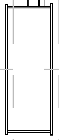
Where can I find how to estimate the welds sizes to built-up a box from independent plates?
Those welds will be fillets over small extensions of the larger plate.
The members is supporting axial bending and torsional loads.
I haven't seen a shear flow for torsional or an example.
Box_Jamb_v2xkwx.png


Thank you.
 
Replies continue below

Recommended for you

Hard to say given that we don't know the proportions of this structure (is it 1" x 3" or 2'x6'?) or the loads.

As a start, do a hand calculation and draw a free body diagram of the forces acting on each plate.

Apply those forces to the weld, treating it as a line. Calculate the resultant of the longitudinal and transverse forces acting on each weld. A 70 ksi electrode strength weld can resist 0.928k per inch length of weld per 1/16" of weld size.
 
Lateral Plates: 15"x0.75"
Up/down plates: 6"x0.5"
Pr 177.392k
Mr33 2721.272k-f
Mr22 0
Vr2 8.278k
Vr3 0
Tr 14.51k-f

I am clear about how to bring the moments such as tension and compression to the flanges and the shears to the corresponding webs, but the torsion? They are opposite shears, and how are they distributed if the plates have different widths and thicknesses? And finally how given them to the line of weld?

Thank you.
 
The shear flow due to torsion is interesting and indeed not often dealt with (to my knowledge) But a quick google search of Composite Sections with Torsion, or Shear Flow due to Torsion. Yields me several results that look promising.

The stress on the welds due to torsion is just another component of stress in a different direction.

If you follow the approach where you just take the vector sum of all stress components on the weld treated as a line you could simply add in the component due to torsion.

Further reading in Blodgetts Design Of Welded Structures has a section on torsional loading that you may find useful.
 
driftLimiter said:
Further reading in Blodgetts Design Of Welded Structures has a section on torsional loading that you may find useful.
Thanks, driftLimiter. This chapter has an example, I will follow it.
 
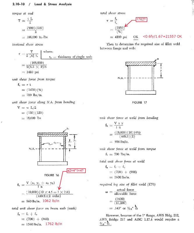
I followed example 5 similar to what I needed, but I found some calculation mistakes.
Can someone look at the correction to see if it is correct?
P%C3%A1ginas_desdeDesign_of_Welded_Structures_Omer_W_Blodg_P%C3%A1gina_1_dp9kxn.png

P%C3%A1ginas_desdeDesign_of_Welded_Structures_Omer_W_Blodg_P%C3%A1gina_2_vazi0v.png


Thank you.
 
I've choked on this myself before. The theory is so dirt simple that I tricked myself into thinking that it must be harder that it was.

Basically, you just multiply the St.Venant shear stress on the red section by the thickness of the cross section there. That becomes the torsional shear flow for use in weld design in exactly the same way that it does when considering the connection between a wide flange beam flange and its web (Mc/I). Easy peasy. And intermittent welding is fine.

c01_fm3og0.png
 
Status
Not open for further replies.

Part and Inventory Search

Sponsor

Top