Continue to Site

Eng-Tips is the largest engineering community on the Internet

Intelligent Work Forums for Engineering Professionals

  • Congratulations waross on being selected by the Eng-Tips community for having the most helpful posts in the forums last week. Way to Go!

GD&T - Bent Tube End Squareness

Status
Not open for further replies.
Replies continue below

Recommended for you

There are infinite ways in which the end face at cut 2 can be parallel to datum A.
It can be parallel to the axis yet diagonal when viewed from the axial direction of the long side.
You either need another datum feature to constrain clocking or use a simultaneous requirement of position + profile or profile + profile with ref. to A to relate the short cylindrical portion and the end face at cut 2.
 
Yes,
The round aspect is clouding my ability to figure out the datums. That and only having used GD&T for rather basics call outs that can reference flat square surfaces.

I have never used profile, but from what I "understand" it can be used in this case.

This one makes sense to me, but not sure if it is correct.
 
 https://files.engineering.com/getfile.aspx?folder=d0a49470-db0c-4c1e-8c52-2dd8c92c160a&file=END_CUT_TOL_B.png
cmart,

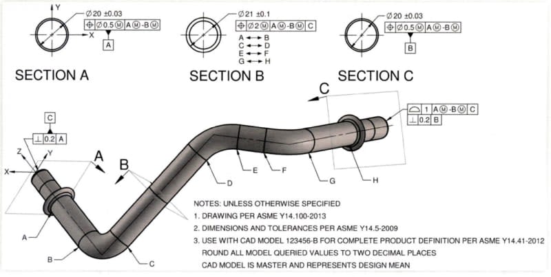
It is better to use a limited length of each end of the tube as a datum feature and control each end face with a profile tolerance to them both as a compound datum feature. This replaces the +/- length tolerances with profile tolerances and basic dimensions. To refine those, use perpendiularity to each individual datum feature appropriate for the end.

It is reasonable in the case of close bends that some other straight section is used as the primary datum feature with the compound datum feature as secondary where the compound datum feature is too small. This would also be used when the datum features at the ends are parallel. For a u-bend - you are on your own.

In many cases profile tolerance is also applied to the various segments of the tube to control straightness and bend angle variations.

Note that for high pressure applications there is usually a specific control for ovality to limit the development of flats or areas of collapse that will produce fatigue failures. In typical specifications this is done with local dimensional control rather than Feature Control Frames as the tube bending operator will not have the capability to make a profile or circularity measurement but can compare the greatest dimension at some section to the smallest at the same section. Neither profile or circularity is controlling the distortion of interest.

See
While the Y14.5 followers tend to believe it solves all problems, specialized industries don't use it.
 
cmart,
What you showed in your attachment from 10 Jul 23 18:52 is a step in the right direction for better defining the orientation of that face.

A couple of things to consider:

1. Datum A is derived from the ID in the long segment. Is there a reason that the OD is used as datum feature B in the short portion?

2. The directly toleranced 90° angle is a problem in terms of providing an unambiguous relationship between the datums being established. Since both datum features are used in the same datum reference frame (for the profile tolerance) their relationship must be basic - implied basic right angle (not explicitly shown). Then to control that relationship datum feature B needs to have a perpendicularity tolerance requirement relative to A. I can expand on why it's so if required, but can changing the plus-minus 3° to a geometric tolerance be acceptable, or do you need to strictly stick to a familiar tolerance?
 
cmart,

I see valid GD&T on your drawing. What bothers me is your tolerances. How accurate is the inside diameter you have specified as datum[ ]A? Is it precise enough to inspect a feature parallel to it to 0.01"? Your length tolerances are reasonably sloppy. If you could pick them up from an outside face, they would be more inspectable.

--
JHG
 
Burunduk said:
1. Datum A is derived from the ID in the long segment. Is there a reason that the OD is used as datum feature B in the short portion?
no, this is just a quick and simple example. I would probably use OD of both, since the inspection is a check fixture that uses the OD.

2. The directly toleranced 90° angle is a problem in terms of providing an unambiguous relationship between the datums being established. Since both datum features are used in the same datum reference frame (for the profile tolerance) their relationship must be basic - implied basic right angle (not explicitly shown). Then to control that relationship datum feature B needs to have a perpendicularity tolerance requirement relative to A. I can expand on why it's so if required, but can changing the plus-minus 3° to a geometric tolerance be acceptable, or do you need to strictly stick to a familiar tolerance?
I would prefer to keep this as simple as possible, using the least GD&T. Most of the parties involved, customer, manufacturer, and myself, have rather basic knowledge of GD&T. One of the most frequent complaints from the customer is end squareness, so I am attempting to define it in a more precise way that can be understood, or easily explained, and inspected.
Customer drawing just has a note that ends must be square within .1"
While the meaning of this is generally understood I would rather have something less ambiguous to hold our overseas manufacturer responsible.

Any additional explanation is appreciated, I am trying to learn more real use applications of GD&T.
 
cmart,
I understand the preference to keep the drawing simple.
However, if the drawing is to be interpreted per a dimensioning and tolerancing standard such as ASME Y14.5, the issue with the directly toleranced angle 90°±3° between datum features A and B is that the datum feature simulators - the devices used to fixture the part and simulate the datum axes at inspection (contracting internal cylinders if the ODs are the datum features referenced regardless material boundary or expanding shafts referenced regardless material boundary if the IDs are the datum features), have no defined angular relationship. If a geometric tolerance such as perpendicularity is used to control the angular relationship, the 90° angle is understood to be a basic dimension without even being specified on the drawing. Then the angle between the simulators is 90°, as accurate as fixtures are built. However, when the drawing requires 90°±3° as shown, one problem is that the requirement is not quite clear regarding how to obtain the axes, and the second thing is that the value of 90° has no unique meaning. Sure, it's right in the middle of the allowed range, but officially it's nothing special and doesn't define the relationship between datum feature simulators. The dimension and tolerance could as well be defined as "87°+6°/-0°" or "87°-93°" and that would not make any difference. So officially you could have various fixtures without a way to know which are correctly made, which is usually not a good thing.
 
2021-08-13_140455_yv7teo_m5rrx0.jpg


from 13 Aug 21 21:12 timestamp from SeasonLee

It's not a great answer, but it's what the SAE thinks will work. The above discussion also includes the SAE reference to the worm gauge.
 
cmart said:
Customer drawing just has a note that ends must be square within .1"

Could the requirement simply mean perpendicularity between end faces?
What if the flat end face of the long section is designated as datum feature A and have some flatness tolerance limiting its form, and the flat end face of the short section has a perpendicularity tolerance with reference to A?
Then the cylindrical features can be toleranced the way you like to keep things simple for everyone as long as functional requirements are met.
 
Burunduk said:
Could the requirement simply mean perpendicularity between end faces?
No, because that would compound the tolerance, so the non-datum side can be off twice as much in relation to the tube legs.

I do want to thank you for your explanations.
I am going to meet wit the customer to find out EXACLY what he needs and what needs to be square to what, and have him amend his tolerances. He is the type of designer that puts 3 decimals on everything with a .005 tolerance, even though he knows that is not realistic, then adds a note or two that a typical skilled shop production guy will understand, but would not hold water when inspected and rejected.
 
cmart said:
I am going to meet wit the customer to find out EXACLY what he needs and what needs to be square to what, and have him amend his tolerances.

Sounds like the right thing to do.
Good luck!
 
Status
Not open for further replies.

Part and Inventory Search

Sponsor