Continue to Site

Eng-Tips is the largest engineering community on the Internet

Intelligent Work Forums for Engineering Professionals

  • Congratulations KootK on being selected by the Eng-Tips community for having the most helpful posts in the forums last week. Way to Go!

Corrugated Structural Plate Design Reference 3

Status
Not open for further replies.

RattlinBog

Structural
May 27, 2022
177
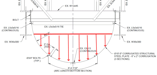
Does anyone know of a design resource or have experience designing corrugated structural plate used as a flume carrying fluid or slurry? See attached section of an existing structure. My goal is to determine the strength of an existing CSP used as a flume.

I found the 8th Ed. Structural Plate Design Guide by Contech, but all the applications are for backfilled pipe or arch culverts supporting AASHTO vehicle loads.
 
 https://files.engineering.com/getfile.aspx?folder=ec8e2415-6682-4b18-bb7f-0a817675c01b&file=corrugated_structural_plate_-_flume_section.jpg
Replies continue below

Recommended for you

Some general guidance might be available in documents that cover design of corrugated steel bins and silos, but probably won't be of much help. The flume's loading will be different than a silo.

You can probably approximate an answer the old way, simplifying assumptions and iterated trial-and-error. Corrugations are "6 inch x 2 inch"... does that mean 2" deep corrugations are spaced 6" on center, or the opposite?

 
SRE, yes, 2" deep corrugation with 6" spacing. Not sure on gage as original reference drawings are incomplete. I'll go out to look at it again with calipers or a UT later. One local engineer suggested I model it in Risa / STAAD as multiple beam elements with a 1 ft width and manually-entered known section properties. I may try that...
 
Isn't this just a half cylinder under pressure? Or am I missing something? If that is the case then just calculate the tension in the steel sheet and ensure the sheet and bolting is suitable for the applied loads.

(I've dealt with corrugated sheet silos and that is pretty much the approach. The complicated bit in silos is working out the appropriate pressure to use.)
 
Yes, you're right. I've got the demand side covered; I was just a bit unsure on the capacity side since it's corrugated plate. Could I just take the cross-sectional area of a 1 ft strip and calculate tensile yielding and rupture?
 
Yep. That is what I would do. The fact that it is corrugated won't affect much under tension, apart from a little higher cross sectional area, but I'd ignore that.
 
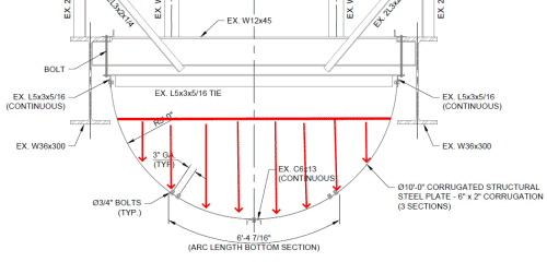
RattlinBog - Since this is an open, essentially horizontal flume carrying fluid (or slurry), isn't load on the corrugated steel from gravity (shown below), not radial loading of a pressurized half cylinder?

corrugated_structural_plate_-_flume_section-50_sddtn1.png
 
SRE, yes my bad, you're right. I was being agreeable earlier but had already calced weight of fluid (attached). I'll refine my numbers a bit later when I have more time, but I believe I'm on the right track. Looks like tension on the steel is about 1500 plf, and the L5x3 tie angle would see about 1000 plf (well more than that based on the L5x3 spacing).

human909, thanks for the help. I was overthinking it...the corrugation tripped me up.
 
 https://files.engineering.com/getfile.aspx?folder=ea710135-f9ba-4565-b236-8887c666fbd4&file=fluid_forces.jpg
If it's a fluid, the pressure still acts perdendicular to the half circle - you've drawn the vertical pressure distribution, but there is also a horizontal pressure distribution
 
Hehehe... Since we are nitpicking, I'll have my shot. [tongue] (I reply in the spirit of fun, not in one of combativeness.) [bigsmile]

SlideRuleEra said:
RattlinBog - Since this is an open, essentially horizontal flume carrying fluid (or slurry), isn't load on the corrugated steel from gravity (shown below), not radial loading of a pressurized half cylinder?

corrugated_structural_plate_-_flume_section-50_sddtn1_zfi4qt.png


Yes, it is gravity but it is still pressure and I'd be drawing my force vectors perpendicular to the corrugated surface unless water recently gain remarkable friction qualities. And naturally the pressure vectors increase with depth. (I sneakily left out the word constant from my previous comment regarding pressure.)

Of course this would result in the half circle deforming into something closer to a subtle parabola if I'm not mistaken.
 
Agreed, my drawing should have been clearer.
The radial pressure on the wall if fairly low (fluid cannot be more than 5' deep) and is not uniform, it varies with depth of the fluid.

Agree with RB about vertical tension load carried by the half circle.

 
Attached is what I ended up with. I need to field verify a couple measurements that I'm currently assuming. It looks like shear rupture at the upper flume-to-angle connection controls. 1.5 klf required < 3.1 klf available
 
 https://files.engineering.com/getfile.aspx?folder=7305828d-ccd8-41e0-b67e-b7c7d834d493&file=Flume_calcs.pdf
Rhetorical questions, not really expecting answered -
[ul]
[li]Is the corrugated multi-piece section a requirement for the process?[/li]
[li]The whole thing looks tedious - it seems like there are other ways to construct this from one piece.[/li]
[li]Is this supposed to be watertight?[/li]
[li]How are you going to rig it?[/li]
[li]Is this assembling on the ground and then being hoisted?[/li]
[li]The fasteners seem oddly assigned - why are there two bolts at each lap, which doesn't see the full load, and only one bolt on each edge? Have you determined the block shear on these fasteners?[/li]
[li]You might be able to evaluate a round non-corrugated flume using the SMACNA round industrial duct construction standards[/li]
[/ul]
 
dvd, this is an existing flume that was constructed in the 1970s. I'm only analyzing it
 
RattlinBog - Your calcs look good to me.

Another subject: Did you complete the project on your 100 year old home?

 
SRE--I appreciate it. I don't expect you to look through with a fine-toothed comb, but I have a couple follow up questions (to you or others).

1) Am I correct in showing that the flume CSP steel will take only the vertical component of fluid pressure; and the L5x3 angle will take the horizontal component? I'm thinking the horiz fluid pressure may put the flume steel into bending, but maybe I don't need to be too concerned about that.

2) Does it seem reasonable that shear rupture at the upper bolt line would control design? I'm making an assumption of 1.5" bolt edge distance until I go take a field measurement (I'm probably not too far off based on photos). Not having worked with this type of design before, I originally wasn't expecting the upper bolt line to control, but now that I see the numbers, it makes sense. Just curious if you see something obvious I missed...

...

Thanks for asking about the house project. It's been a slow and steady wins the race type of work. I've been working on it once or twice a week, usually Saturdays, for the last two months. All my problem joists are now sistered, and I'm planning to reinforce my main beam this weekend. I have some joist blocking to install too. I've been able to improve a few areas that were sagging slightly or creaking. I was also able to double up my trimmer joists that are picking up the stairwell header. One of the trimmers was cut in half for hvac years ago and caused neighboring joists to become overstressed. Somebody did some partial scab repairs, but I ripped those out and put in full length, full depth joists.
 
RB - Your solution assumes that CSP is rigid (even when loaded) which makes the analysis a straight-forward statics problem. Not totally true, but pretty good for CSP... there is an operational issue with slurry that will make this error seem like peanuts... I'll get into that later.

1) Solving with statics, agree that CSP supports only the vertical slurry load.

The L5x3 is assumed to take all horizontal load. Think of as being somewhat like a cantilever retaining wall. With a horizontal support at the top of the retaining wall, the wall is assumed to be a simple span with triangular loading. Without the horizontal support at top of the retaining wall, the wall is... cantilevered with triangular loading.

2) Shear rupture controlling does not surprise me. Fairly common mode of failure; believe the 2007 sudden collapse of the bridge in Minneapolis, MN was caused in part by shear rupture of undersized gusset plates.

Slurry Issues: I've had projects at our coal-fired electric generating stations involving slurry (from thickener underflow of limestone-based, wet flue gas desulphurization systems, i.e. "scrubbers").

Slurry is water containing suspended solids. In your case 75 pcf = 62.4 pcf (water) + 12.6 pcf (suspended solids). Without near constant agitation, the solids will settle out of suspension. The solids from our system are "sticky" and tend to build up on surfaces. The same will almost certainly happen to your project's flume. Suggest checking with plant operations on the properties of solids and include an allowance in your loading for solids buildup.

An example of how bad this can get. Inside one scrubber, a structural beam was had solids so thick that it visibly deflected, say, about L/50. Had to come up with a way to increase beam's moment of inertia without removing it.

Seems like your are continuing to upgrade your house the right way... excellent.

 
RattlinBog said:
1) Am I correct in showing that the flume CSP steel will take only the vertical component of fluid pressure; and the L5x3 angle will take the horizontal component? I'm thinking the horiz fluid pressure may put the flume steel into bending, but maybe I don't need to be too concerned about that.
No.

The horizontal component is completely resolved by tension in the shell.

For an rigid undeformed shell there is no horizontal component on the L5x3 angle.

For a flexible shell there is a small horizontal component in the OPPOSITE direction to what is shown in your calculations.

temp_jttn6t.png

Have another look at your pressure arrows. They all cancel out in the horizontal direction! Thus there is no Rh resultant force if you assumer a rigid shell. (But we don't have a rigid shell it is flexible and as said it pulls in the opposite direction.

Another way of thinking about it is if you pick up water with a thin flexible membrane held between you two hands. What loads are you hands feeling? ANSWER vertical loads and some inward loads PULLING your hands together.


(I haven't gone through your calculations though I'd think you would be underestimating the tension there as you have ignored the horizontal components.)
 
human909, I had to think about this for a bit, but I believe I understand what you mean. I see that the horizontal fluid pressure cancels out. I'm having a hard time imagining picking up water in a thin membrane with my hands; but I have a better time imagining a sagging powerline or someone walking on a tightrope...not exactly fluid pressure, but maybe it's similar enough. The tension in a sagged cable approaches infinity as sag distance approaches 0. Does a sagged cable powerline push the poles outward? No, it wants to pull them together. If I pretend my flume is flexible like a sagged cable, I can visualize how it wants to pull its top end connections together...hence the L5x3 angle would actually be in compression. If the flume was perfectly rigid, I can see how there is no horizontal reaction.

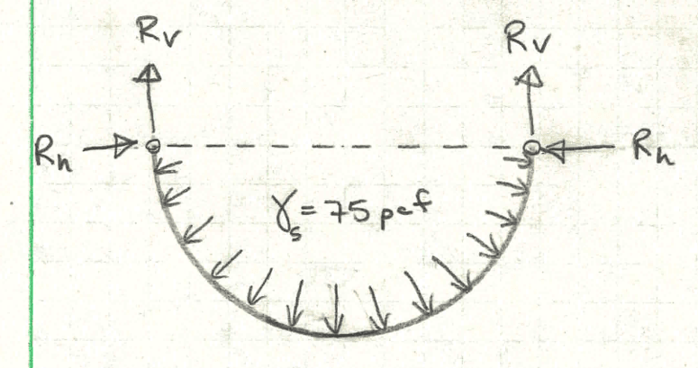
The tension in my flume steel will be the resultant force from the vertical and horizontal components. However, I believe the top bolt line connection will still only need to resist the vertical component for shear rupture since the flume steel is vertical at that point...but that's probably splitting hairs, and I can just check that bolt line for the full tension. See attached FBD I crudely made in Strian...not exactly a semi-circle, but it helped me see what's going on.

I think what tripped me up was that I was first visualizing a flume supported on its bottom surface instead of hanging from the top. In a bottom support scenario, the fluid wants to collapse the flume and push its unrestrained top ends outward. In a top hanging support, the fluid pushes the flume down, but then the flume tension (not the fluid) wants to pull the top supports in. I think I'm squared away now. Thank you!


SRE, definitely agreed about solids buildup. This absolutely does happen in this flume, and I will bump up dead load to take it into account. My main objective is to analyze the existing strength of the flume as we're seeing some corrosion issues.
 
 https://files.engineering.com/getfile.aspx?folder=05eb9541-cc21-4ef9-a0f1-18a637ac990b&file=flume_fbd.jpg
RattlinBog said:
human909, I had to think about this for a bit, but I believe I understand what you mean. I see that the horizontal fluid pressure cancels out. I'm having a hard time imagining picking up water in a thin membrane with my hands; but I have a better time imagining a sagging powerline or someone walking on a tightrope...not exactly fluid pressure, but maybe it's similar enough. The tension in a sagged cable approaches infinity as sag distance approaches 0. Does a sagged cable powerline push the poles outward? No, it wants to pull them together. If I pretend my flume is flexible like a sagged cable, I can visualize how it wants to pull its top end connections together...hence the L5x3 angle would actually be in compression. If the flume was perfectly rigid, I can see how there is no horizontal reaction.
Exactly.

RattlinBog said:
The tension in my flume steel will be the resultant force from the vertical and horizontal components. However, I believe the top bolt line connection will still only need to resist the vertical component for shear rupture since the flume steel is vertical at that point...but that's probably splitting hairs, and I can just check that bolt line for the full tension. See attached FBD I crudely made in Strian...not exactly a semi-circle, but it helped me see what's going on.
Correct.

There is a slight additional inward pull due to the behaviour I have pointed out and you have now recognised, but it seems to be less than a 10% increase. If your focus is on the bolt line then vertical is a very close approximation.

A chain or sagged cable forms a catenary shape. This has an increasing line load towards the centre so the actual shape is likely even more complicated or at least a variation on a catenary equation. I can't claim to have done the calculations. It would get quite complicated quite quickly to do it suitably. But I believe I have a general grasp on the behaviour.
 
Status
Not open for further replies.

Part and Inventory Search

Sponsor