Continue to Site

Eng-Tips is the largest engineering community on the Internet

Intelligent Work Forums for Engineering Professionals

  • Congratulations KootK on being selected by the Eng-Tips community for having the most helpful posts in the forums last week. Way to Go!

Reactions to an offset pinned constraint 1

Status
Not open for further replies.

David2065

Student
Jul 19, 2023
3
Hi

I was wondering if someone could help me explain a conundrum I'm having?

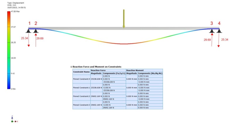
I have a steel section slung between to I beams with a load equally positioned in the center ( The I beams are 2.5m apart ) With a load of say 8kN on two constraints I get an equal division of the load including the beam weight. If I have two pinned constraints on each end of my beam, the reaction forces increase massively, one at 25kN and the end one at -29kN. How is this explained.

Thanks in advance

Dave

 
 https://files.engineering.com/getfile.aspx?folder=c24dc2a5-fdb5-4622-9cf6-153a29288fd9&file=4_contraints.jpg
Replies continue below

Recommended for you

Simple, you essentially have a moment reaction between the two supports at each end. The outer supports have a downward load to keep the ends from displacing upwards as the beam rotates around the inner supports.
 
Great thanks, that is what I thought, but why the 25kN reaction against the first constraint with only a 8kN load?
 
because the inner reaction load is also a function of the outer reaction load. if you sum all 4 reactions it should equal 8kN.
 
The 25kN comes from 2 places:

1/2 of 8kN weight (29-25) and
whatever it takes to bend the beam on the ends to keep zero displacement on each support.
 
your picture is very misleading. Your beam is effectively fixed-fixed ... the pair of closely spaced pinned supports works like a fixed end. Each end is reacting 29kN down and 25kN up, nett 4 kN at each end, reacting your 8 kN load. Show the numbers of the supports; I think they are (Left to Right) 1-2-3-4 ... once written it's obvious but the order in the table made me think it was 4-1-2-3 ...

"Hoffen wir mal, dass alles gut geht !"
General Paulus, Nov 1942, outside Stalingrad after the launch of Operation Uranus.
 
Thanks for your help everyone.. very much appreciated..
 
Reaction = 29.69 - 25.34 = 4.35kN each end;
Total load = 8.70kN, so beam weighs 0.7kN
End moment M = 25.34a kN-m where a is the length 1-2 and 3-4.
Doesn't look like a problem.

Capture_soabhi.jpg
 
You don't have a one span; you created a 3 span continuous beam, with a very large span ratio. If the I-beams are restrained against torsional rotation where your beam is connected, the reactions at the edges of the flanges may approach the reactions in your analysis. However, if the I-beams are not restrained against torsional rotation (twisting), then the I-beams will twist, and approach the reactions and moments of a beam with simply supported ends. If you want an accurate representation of the load effects on the beam, you have to model it with the end restraint that mimics the torsional stiffness of the I-beams at the location where your beam is attached, and the stiffness of the connection between your beam and the I-beams.

For a conservative design of the beam, model the connection to the I-beams as a single pinned connection at each end.
 
Status
Not open for further replies.

Part and Inventory Search

Sponsor