Continue to Site

Eng-Tips is the largest engineering community on the Internet

Intelligent Work Forums for Engineering Professionals

  • Congratulations waross on being selected by the Eng-Tips community for having the most helpful posts in the forums last week. Way to Go!

HSS Fully Welded Moment Connection to Wide Flange

Status
Not open for further replies.

EngDM

Structural
Aug 10, 2021
378
Hey all,

I was hoping someone here would have a reference or an example for connecting a cantilever post (HSS) to the top flange of a roof beam (T connection). The intent is for a frame to be built on the roof, and providing a fully welded connection to the wide flange. I can't find anything using RISA Connection or IDEA Statica for this specific type of connection to try and get a reference. The loads are relatively low, but I'm struggling to justify if a 1/4" fillet all sides would be sufficient or if I should prep the HSS and CJP it to the beam.
 
Replies continue below

Recommended for you

Just calculate the section modulus of the weld and compare it against the moment. Do a quick conservative check of the flange against point loads as well, using a 45 degree line of action.
 
I'd have to think that the fillet welding would be fine for small loads. You might want to put a pair of stiffeners under the crossing HSS walls. That or, if more is required, half section HSS stubs as stiffeners.
 
KootK said:
I'd have to think that the fillet welding would be fine for small loads. You might want to put a pair of stiffeners under the crossing HSS walls. That or, if more is required, half section HSS stubs as stiffeners.

EOR is calling for showing 3/8" stiffeners under the HSS centers. I'd imagine this is plenty to stop the flanges from bending upwards/downwards.

canwesteng said:
Just calculate the section modulus of the weld and compare it against the moment. Do a quick conservative check of the flange against point loads as well, using a 45 degree line of action.

Pardon my ignorance, but can you elaborate on comparing the section modulus to the moment? Do you mean calculating the Srequired for the moment load and comparing it vs that? I have Table 3.2 from some reference, but I don't know what source it references. I believe it is from one of the design guides but I can't be sure.
Screenshot_2023-07-24_145151_ba8t15.png


If stiffeners are being provided, does the flange need to be checked against point loads? Do you have a reference for this calc?

Apologies again, still pretty green when it comes to connections that aren't directly specified in AISC or CSA.
 
There are many design options at your disposal, but the optimal one depends of your specific conditions.

You're not going to need to CJP an HSS to the beam flange if your loads are "relatively small." Also, if you're building a frame on top of the roof, you might be working with galvanized members. Is this welded in the field? The more descriptions you give, the more precise the answers will be, and a sketch goes a long way.
 
DrZoidberWoop said:
Also, if you're building a frame on top of the roof, you might be working with galvanized members.

The frame will be encased in drywall, they are building a larger parapet on top of the existing roof beams. The members are not galvanized.
 
EngDM: The snip in your post is from Design of Welded Structures by Omer Blodgett. A resource worth having. If you notice the units from the modulus equations in the table will be in square mm (not cubic), because Blodgett calculates based on a line method. Before using those equations please grab a copy of his book so you can understand the process. Here are some Eng-Tips links about it thread 1 (scroll down to Megastructures post half-way through the thread), thread 2.

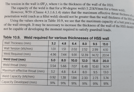
I've posted the table below before and it shows that you can achieve 91% efficiency with a pretty reasonable fillet. It comes from Structural Steel for Canadian Buildings: A Designer's Guide. Sorry for the Cannuck units. (seems you are a fellow Canadian!). For small loads your limiting factor probably is local effects on the W-section.

Capture_wf1lun_qo63s1.png
 
Enable said:
The snip in your post is from Design of Welded Structures by Omer Blodgett. A resource worth having.

I have a copy of this, however the page number format doesn't match my screenshot.
 
Enable said:
I've posted the table below before and it shows that you can achieve 91% efficiency with a pretty reasonable fillet. It comes from Structural Steel for Canadian Buildings: A Designer's Guide. Sorry for the Cannuck units. (seems you are a fellow Canadian!). For small loads your limiting factor probably is local effects on the W-section.

The table you posted, does this imply that you must use the weld specified under each column? For instance, for 6.4mm HSS you must use 10mm fillet to develop 91% the capacity of the HSS? I'm assuming this is for a weld on all sides as well.
 
You can go very deep into the topic if you want, but if 1) the max fillet weld your HSS can handle is a single pass weld and 2) your loads really are small compared to HSS capacity, I'd probably spec the weld to "develop" the HSS wall and move on.

D_max_HSS(LRFD)=0.75*0.6*Fu_HSS*HSS_Wall_Thickness/1.392

Alternatively, you can go into the minutia of the elastic method calcs and find the "exact" result you're looking for. If that's what you want to do, you'll find Alex Tomanovich's old excel spreadsheet useful. It's around the internet in plenty of places.


DrZoidberWoop said:
Alternatively, you can go into the minutia of the elastic method calcs and find the "exact" result you're looking for. If that's what you want to do, you'll find Alex Tomanovich's old excel spreadsheet useful. It's around the internet in plenty of places.

This is what I have been using. Since this calculates the force in the weld, is it as straight forward as comparing the force in the weld to the weld strength and bobs your uncle? And then of course checking the beam flange for local effects.

The formula you gave above, are the units imperial? The 1.392 factor makes me think it has some baked in constants that won't translate to metric units.
 
EngDM said:
I'd have to think that the fillet welding would be fine for small loads. You might want to put a pair of stiffeners under the crossing HSS walls. That or, if more is required, half section HSS stubs as stiffeners.

No doubt. The presence of the stiffeners is relevant to your assignment because they will both constrain and simplify your weld design. Any axial stresses in the HSS walls will need to get transferred through only the welds that are located above the stiffeners.
 
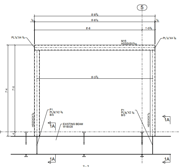
Screenshot_2023-07-24_153845_nd0q6b.png


Here is what is detailed currently. I believe the bottom connection to the beam will be sufficient, however the top corner connections is something I haven't tackled before either. I think I'd rather see the vertical posts continuous to the top and the horizontal member welded into it as opposed to running on top. I'd imagine I need some sort of plate added to really develop the moment connection.
 
DrZ... in your equation D_max_HSS(LRFD)=0.75*0.6*Fu_HSS*HSS_Wall_Thickness/1.392, can you explain the value 1.392 and the Fu for the weld material?

-----*****-----
So strange to see the singularity approaching while the entire planet is rapidly turning into a hellscape. -John Coates

-Dik
 
dik - 1.392 is the AISC LRFD capacity (the specific reference to this value can be found somewhere in Chapter 9 of the manual I believe) of a 70ksi tensile strength electrode fillet weld per inch per 16th of weld leg....0.75*0.6*70*0.707*0.0625 = 1.392 kip/in/16th. Such a great number, perhaps tattoo worthy even.

Equivalent ASD number is 0.928. For this weld just do the elastic method, the practice will be good and once you're used to the method it will only take a few minutes to check, especially with the ol' 1.392. If it's truly light loads, 1/4" fillet all around will be plenty.
 
Thanks... I calculate the section property of the weld (treating it as an ellipse if on a slope). All part of my guard and handrail design programs.

-----*****-----
So strange to see the singularity approaching while the entire planet is rapidly turning into a hellscape. -John Coates

-Dik
 
Dik,

As mentioned above 1.392 is the "fillet weld factor" as derived on AISC SCM pg 8-8. The 0.6*Fu comes from the Base Metal portion of Table J2.5 (AISC SCM 16.1-124) and is plugged into the equation

D_max_HSS=Code_Factor*0.6*Fu_HSS*HSS_Wall_Thickness/(Number_of_Fillets*Fillet_Weld_Factor)

to calculate the maximum fillet weld a given connection component can handle. It's the longer form equivalent to Equations 9-2 & 3: t_min=3.09D/Fu or t_min=6.19D/Fu(AISC SCM pg 9-5)

W/ Code_Factor= 1/2(ASD) or 0.75 (LRFD); Fu_HSS=Tensile/Rupture stress of base metal(AISC Table 2-4); Fillet_weld_Factor = 0.928 (ASD) or 1.392 (LRFD) AISC SCM pg8-8.

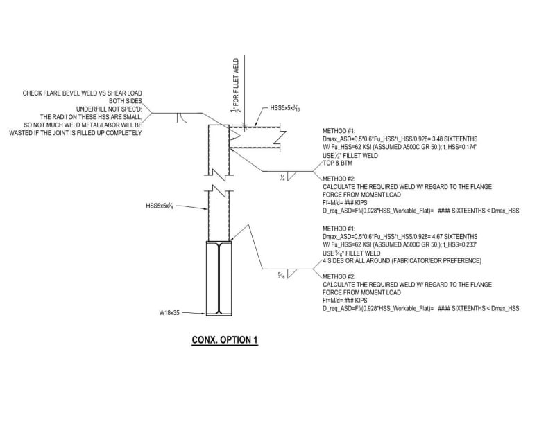
Edit: OP. I've attached one method of design you can consider. There are many more weld/frame orientations you can use, including using plates/bolted conx. I don't have any more time this morning, but good luck.
I_HATE_HSS_TO_HSS_CONX_gw8h3x.jpg
 
Status
Not open for further replies.

Part and Inventory Search

Sponsor