BulbTheBuilder
Structural
A friend of mine with no building knowledge asked me to review a structural drawing for him which kind of looks messy to me. The engineer used metric units and Eurocode to design which I am not typically familiar with. Regardless, concept of design is basic across all design codes and things in the drawing set don't make sense to me.
The structure is meant to be a concrete braced frame with isolated footing. The region has non-seismic activities and the wind speed for MRI 700 years is less than 40mph, somewhere in Africa and the code the "engineer" used is Eurocode. Now, I am not typically familiar with Eurocode as a result, I don't know if there governing clauses on why certain things were done. I asked my friend to reach out to the engineer for clarification on certain concerns and questions, but the engineer is claiming everything has been done per code. To make things easier, I requested for snapshot of pages of the code but he is adamant to produce any and I don't have a copy of the Eurocode myself.
I would appreciate anyone familiar with Eurocode to provide any feedback since most things shown the drawing don't seem right.
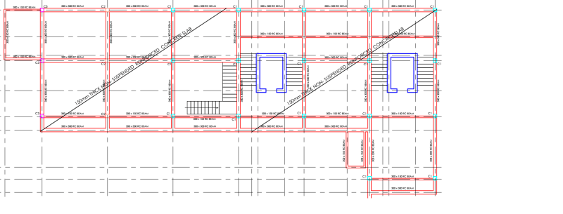
For isolated footing, why have all these 300mmx300mm (approximately 12"x12") ground beams. I see no reason or use of them unless they were meant for the edges of the slab as restraints.

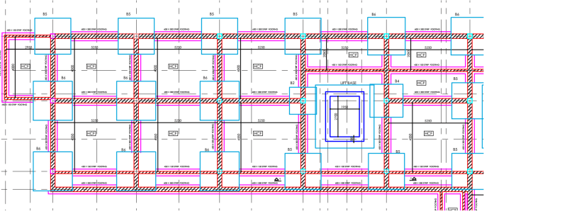
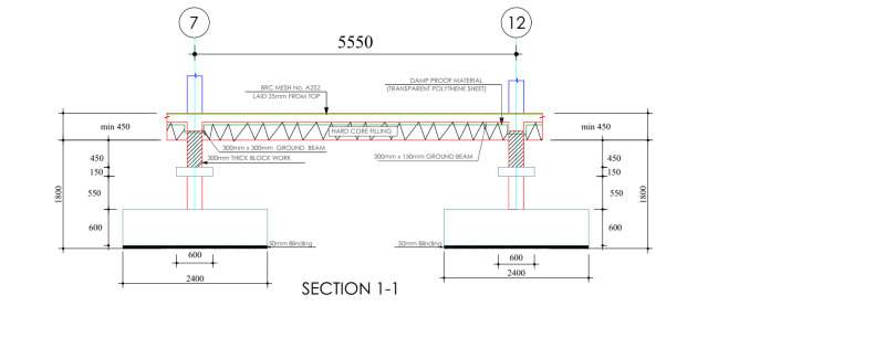
And why add strip footing and 300mm (12" thick)CMU for a slab on grade? Is it something recommend in European code?

The slab is a slab-on-grade supported just on the soil which has a bearing capacity of 250kN/m2 (`5220psf). The soil is more than adequate to hold the slab so why go extra mile to even add 12" solid CMUs?

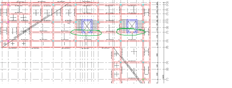
The interesting part is the shear wall. The shear wall from the drawings is "disconnected" from the building and only has 1 beam connecting to it. All other side of the shear wall is then unbraced from ground to roof level (5 levels with 4m~12feet floor-to-floor) as they have a staircase around. Although, the wind speed isn't high I am not comfortable seeing such a general arrangement as the shear walls are basically useless in the scenario and the columns will need to be designed as unbraced frames rather than braced.

I have not completed my review on the drawings, but I am seeing a lot of questionable items I have decided not to proceed any further. I am tempted to tell me friend the "engineer" is probably a guy dumping things a software application like the Midas guy but I am being respectful and holding back any comments for now.
The structure is meant to be a concrete braced frame with isolated footing. The region has non-seismic activities and the wind speed for MRI 700 years is less than 40mph, somewhere in Africa and the code the "engineer" used is Eurocode. Now, I am not typically familiar with Eurocode as a result, I don't know if there governing clauses on why certain things were done. I asked my friend to reach out to the engineer for clarification on certain concerns and questions, but the engineer is claiming everything has been done per code. To make things easier, I requested for snapshot of pages of the code but he is adamant to produce any and I don't have a copy of the Eurocode myself.
I would appreciate anyone familiar with Eurocode to provide any feedback since most things shown the drawing don't seem right.
For isolated footing, why have all these 300mmx300mm (approximately 12"x12") ground beams. I see no reason or use of them unless they were meant for the edges of the slab as restraints.

And why add strip footing and 300mm (12" thick)CMU for a slab on grade? Is it something recommend in European code?

The slab is a slab-on-grade supported just on the soil which has a bearing capacity of 250kN/m2 (`5220psf). The soil is more than adequate to hold the slab so why go extra mile to even add 12" solid CMUs?

The interesting part is the shear wall. The shear wall from the drawings is "disconnected" from the building and only has 1 beam connecting to it. All other side of the shear wall is then unbraced from ground to roof level (5 levels with 4m~12feet floor-to-floor) as they have a staircase around. Although, the wind speed isn't high I am not comfortable seeing such a general arrangement as the shear walls are basically useless in the scenario and the columns will need to be designed as unbraced frames rather than braced.

I have not completed my review on the drawings, but I am seeing a lot of questionable items I have decided not to proceed any further. I am tempted to tell me friend the "engineer" is probably a guy dumping things a software application like the Midas guy but I am being respectful and holding back any comments for now.

![[wink] [wink] [wink]](/data/assets/smilies/wink.gif) ) for sites where concrete batch size/delivery is challenging. If not specifically jointed, the restraint is detrimental to slab performance, and a thickened slab with 3:1 transitions would be better.
) for sites where concrete batch size/delivery is challenging. If not specifically jointed, the restraint is detrimental to slab performance, and a thickened slab with 3:1 transitions would be better.