milkshakelake
Structural
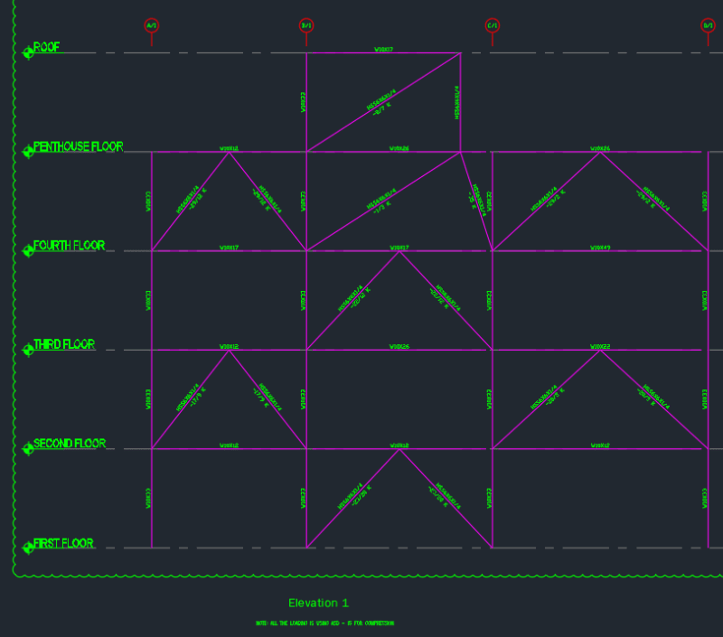
Is this an in-plane discontinuity in the seismic system? Here's what my framing looks like:

I know it's not the best, but I did this years ago. Now it's under audit and a regulator is saying it's a vertical irregularity, which I tend to agree with. However, I would like to defend myself. From my understanding, a vertical in-plane discontinuity would impart overturning moment-load-transfer discontinuity. This would require amplified forces for the columns and the collectors (horizontal link connections between bays).
In this case, I'd say that the entire vertical lateral system is one big truss, so there is no discontinuity. I'm not sure how I'd justify that reasoning or if it makes sense, so I'm looking for some guidance.
For context, the applicable code is ASCE 7-10, seismic category is B, and the following code applies:
For some justification on my thought process, this situation is fundamentally different than something I found in 2012 IBC SEAOC Structural/Seismic Design Manual that explains this irregularity:

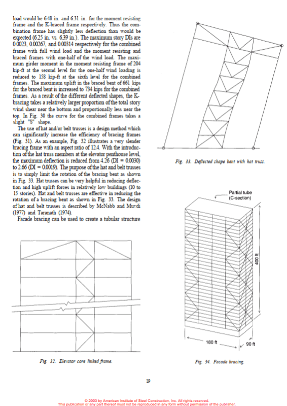
The fundamental difference is that the offset shear wall is not strictly connected to a direct vertical load path, whereas in my case, it's like a truss with staggered diagonal supports that all connect. My situation is more akin to what is described in AISC Design Guide of Low-Mid Rise Structures, showing a hat truss concept:

Sorry if this doesn't make a lot of sense, which is why I'm posting here.

I know it's not the best, but I did this years ago. Now it's under audit and a regulator is saying it's a vertical irregularity, which I tend to agree with. However, I would like to defend myself. From my understanding, a vertical in-plane discontinuity would impart overturning moment-load-transfer discontinuity. This would require amplified forces for the columns and the collectors (horizontal link connections between bays).
In this case, I'd say that the entire vertical lateral system is one big truss, so there is no discontinuity. I'm not sure how I'd justify that reasoning or if it makes sense, so I'm looking for some guidance.
For context, the applicable code is ASCE 7-10, seismic category is B, and the following code applies:
Table 12.3-1. In-Plane Discontinuity in Vertical Lateral Force-Resisting Element Irregularity: In-plane discontinuity in vertical lateral force-resisting elements irregularity is defined to exist where there is an in-plane offset of a vertical seismic force-resisting element resulting in overturning demands on a supporting beam, column, truss, or slab.
12.3.3.3 Elements Supporting Discontinuous Walls
or Frames - Columns, beams, trusses, or slabs supporting discontinuous walls or frames of structures having horizontal irregularity Type 4 of Table 12.3-1 or vertical irregularity Type 4 of Table 12.3-2 shall be designed to resist the seismic load effects including overstrength factor of Section 12.4.3. The connections of such discontinuous elements to the supporting members shall be adequate to transmit the forces for which the discontinuous elements were required to be designed.
For some justification on my thought process, this situation is fundamentally different than something I found in 2012 IBC SEAOC Structural/Seismic Design Manual that explains this irregularity:

The fundamental difference is that the offset shear wall is not strictly connected to a direct vertical load path, whereas in my case, it's like a truss with staggered diagonal supports that all connect. My situation is more akin to what is described in AISC Design Guide of Low-Mid Rise Structures, showing a hat truss concept:

Sorry if this doesn't make a lot of sense, which is why I'm posting here.

