Eng-Tips is the largest engineering community on the Internet

Intelligent Work Forums for Engineering Professionals

  • Congratulations waross on being selected by the Eng-Tips community for having the most helpful posts in the forums last week. Way to Go!

Piggybacked trusses

Status
Not open for further replies.

RontheRedneck

Specifier/Regulator
Jan 1, 2014
217
US
This subject came up the other day, and I said I'd try to do a thread on it.

I figure most of you know a lot about them. So there are only a couple of practical things I can talk about that might be helpful.


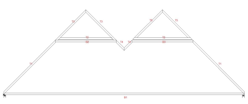
I created this fictitious truss to show one of the things I'd like to suggest to any of you who deal with piggybacked trusses. Note that the 2 caps are different.
PB_example_fthwm7.jpg


The cap on the left has extended top chords that go to the flat TC on the base truss. This is the most common type of cap that I see.

Of course the design of the base truss requires that the flat TC of the base truss have 2X4 purlins on it, and the cap sits on top of them. That's documented in the packet of information that we send out with the trusses. (The same packet that usually gets thrown in the trash as the truck pulls off the jobsite)

I do caps like the one on the right. The TC of the cap does not extend down to the flat TC on the base truss. So if the framer has no clue what they're doing, they'll call us and tell us the cap trusses don't fit. Then we can explain to them what needs done. And there's a much greater chance that the purlins will actually get installed.


If a base truss is really large, the flat TC can be sheathed with plywood. Alpine typically recommends or requires that in some cases. Such as:

The flat TC of the base truss is more than half the span.
The flat TC has more than 5,000# of compression
If it's a double cap. (i.e. the cap truss is capped)

I think this is a good idea on really long span or exceptionally tall trusses, for a couple of reasons.

One is that it does a much better job of bracing the flat top chord of the brace truss. It also gives the workers a flat platform to work off of to set the base trusses.

If any of you work with large PB trusses I'd suggest considering it.
 
Replies continue below

Recommended for you

I very much like the sheathing at the TC, but it can make it difficult to inspect or access the caps in the future.
 
Thanks, Ron. I'll second the sheathing for bracing on the base truss, as well as some significant out of plane bracing. I've seen one nearly catastrophic failure of a very large church where they installed "bracing", but it was just straight 2x4's flat between the base and the piggy back nailed off to the end wall. There was no actual bracing load path, so the whole place shifted. It was a few years ago....I think the worst was something like 18" out of plane? The best part...I didn't know what I was dealing with until I was in the truss system, 40 feet off the deck, taking measurements to analyze for new loading.
 
RPGs - There's no reason an access hatch can't be allowed for. There has to be some sort of opening for ventilation anyway.


phamENG - The worst failure I ever saw was a church. ~70' wide gym with ~16' tall CMU walls. Large PB trusses.

The framer set the base trusses and put the rows of purlins on the flat top. But they were not braced to anything. There were no braces at all on the BC or on the sloped TC.

After they set all the trusses they thought it would be a good idea to use the crane to set some bunks of plywood on the flat tops of the trusses. Of course the trusses buckled and went down. Nine guys went with them. By the grace of God none of them were killed.


Will poke--thanks Ron. Love your posts, keep them coming.
 
If you sheath the flat TC, how are the PB trusses attached?
 
Are there supposed to be two pictures?

Both caps look identical to me

Remember - More details = better answers
Also: If you get a response it's polite to respond to it.
 
They are not. Look at where the top chord meets the base truss. The one on the left continues all the way down to sit on the base truss while the one on the right has its top chord resting on its own bottom chord. If you set the one on the right without putting the requisite 2x4 flat bracing on top of the base truss, the top chords won't line up and your roof plane will have an ugly step in it. That's why Ron is suggesting it's a good way to ensure they put it in.
 
The one on the right is what I visualize when we talk about Piggy Back trusses. The usual reason is that without the piggy-back feature, the truss is too tall to clear bridges during transportation to the site.

I don't understand the one on the left. Member T4 seems to be part of the main truss. So it isn't clear how the PB truss can be separated from the main truss.

A better design, imo, is to terminate the main truss at the point where the two T4 members meet, then let the PB trusses just sit on top without contributing one iota to the strength of the combined truss.
 
XR250 asked "If you sheath the flat TC, how are the PB trusses attached?"
The plywood is typically held back from the ends. That allows ventilation. And scabs connect the caps to the base truss.

LittleInch said "Both caps look identical to me"

Sorry that the picture isn't very clear. I assume the website shrinks them to save bandwidth.

This closeup at the center will hopefully make the difference clear:

PB_closeup_un6ics.jpg


BAretired said: "The usual reason is that without the piggy-back feature, the truss is too tall to clear bridges during transportation to the site."

Actually it's limited by the width of production tables. They're typically 14' wide.

You can't build a 14' truss though - You have to leave room for blocks to form the shape of the truss. We limit the height of trusses to 13' 2".
 
That was my eyesight not picking up the difference....

Is the gap for the one on the right supposed to be there? Or is this the gap to fit some bracing between each lower truss?

Remember - More details = better answers
Also: If you get a response it's polite to respond to it.
 
RtR said:
The plywood is typically held back from the ends. That allows ventilation. And scabs connect the caps to the base truss.

Got it. Are the bottom chords then designed to clear span for uplift?
 
LittleInch asked: "Is the gap for the one on the right supposed to be there?"

The flat TC of PB trusses require purlins 2' OC. Have another look at the OP.


XR250 asked: "Are the bottom chords then designed to clear span for uplift?"

Theoretically the BC is attached to all of the purlins, so it's braced. In reality I doubt that gets done very often.

I have never run across a case where the lack of bracing caused any problems. I have heard of cases where the flat TC of PB trusses has buckled. But I am not aware of any cases of problems with caps.
 
Ron.

It's just different terminology. Purlins to me are mid rafter span at at their longer side inside so the 2"bit sits against the rafter.

I would call your 2 x 4 (which lies flat?) a truss support connector or something similar.

But it makes total sense, just not shown on the drawing so I wasn't quite sure.

Remember - More details = better answers
Also: If you get a response it's polite to respond to it.
 
Fair enough.

The names of various thing varies a lot from one area of the country to another. I guess it would be the same for purlins.
 
In the sketch below, the red members are the piggy back trusses which attach to the main truss shown in black. The main truss carries all the roof load, with 3 point loads and a uniform snow load in each of the end panels. Do I have it right?

Capture_yhjqoh.jpg
 
Your sketch is correct in how they fit together. Although the gap appears to be exaggerated.


Design methodology varies.

One place I worked at left the uniform dead load evenly distributed. But the live load was a point load at the end of the caps. (They did cap trusses with the extended TC)

Another one designed the caps, and then transferred the loads to the base truss through the software. (Mitek software)

We just design the base truss with uniform live and dead loads as if it were the only truss. Since the cap truss is supposed to be supported on purlins every 2' - And we don't do the extended TC - That seems reasonable to me.


There are as many opinions about how that should be done as there are engineers.
 
Thanks Ron for the quick response.

Ron said:
Your sketch is correct in how they fit together. Although the gap appears to be exaggerated.
To me, the gap looks about right if the goal is to minimize top chord bending moment, but there may be other considerations.

Ron said:
We just design the base truss with uniform live and dead loads as if it were the only truss. Since the cap truss is supposed to be supported on purlins every 2' - And we don't do the extended TC - That seems reasonable to me.
In this example, the base truss could be designed as if it were the only truss. The base truss moment cannot be larger than the simple span moment (although I might have some concerns about additional snow load collecting in the valley between caps).

I would not use purlins at 2'-0" centers to support the caps. Each cap truss can span end to end without any help from the purlins, in fact purlins simply add bending moment to the cap BC and the base truss TC. Extending the cap top chords down to the base truss permits a point load at each end of each cap.
 
Cap trusses are not designed to bear at the extended top chords. To the best of my knowledge no one does that.

The purlins are needed to keep the flat TC on the base truss from buckling. And the cap truss bears on them. That's the industrious standard for piggyback truss design.

The truss in the OP was a fictitious truss so I could show both types of caps side by side. No need to worry about drift loading.
 
Status
Not open for further replies.

Part and Inventory Search

Sponsor

Back
Top