First time posting here - always use this forum when searching for info and finally decided to join the community. Let me know if you need more info.
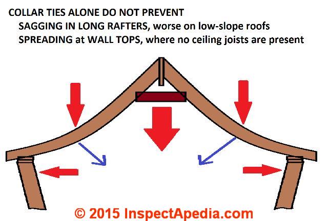
I am looking to design a compression roof with no ceiling joists/ties, or structural ridge beam. I am hoping to use a ridge board and collar ties. Is this possible?
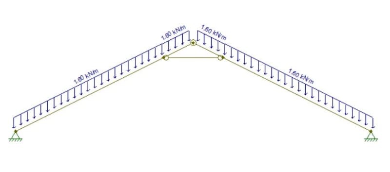
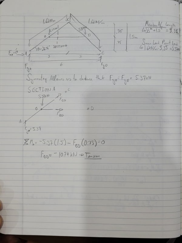
I have 2 of these to design but the one I am most concerned about has a low pitch of 3/12, dimensions are about 6m wide x 1.5m tall
My concern is that the walls kick out due to heavy snow loads (2.3kPa).
Diagram below and a website delving into the issue.
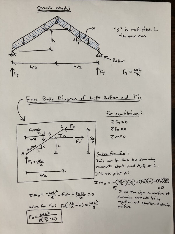
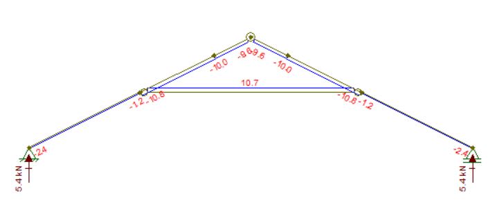
I am trying to model this roof on FTool but having a difficult time understanding if I am analyzing correctly. I tried playing around with height of collar tie and even adding a ceiling joist but unable to reduce the lateral load to something acceptable which tells me my model is not acting right.
Model:
Modeled with high collar tie:
Also, the way I picture the load transfer is that the lateral load has to be carried by the top plate of the wall (double 2x6) it bears on. And that the top plate acts as a beam from shear wall to shear wall. The top plate will run 4m from shear wall to shear wall and a double 2x6 is not that strong so the load would have to be quite minimal. Am I analyzing this correctly?
I am looking to design a compression roof with no ceiling joists/ties, or structural ridge beam. I am hoping to use a ridge board and collar ties. Is this possible?
I have 2 of these to design but the one I am most concerned about has a low pitch of 3/12, dimensions are about 6m wide x 1.5m tall
My concern is that the walls kick out due to heavy snow loads (2.3kPa).
Diagram below and a website delving into the issue.
I am trying to model this roof on FTool but having a difficult time understanding if I am analyzing correctly. I tried playing around with height of collar tie and even adding a ceiling joist but unable to reduce the lateral load to something acceptable which tells me my model is not acting right.
Model:
Modeled with high collar tie:
Also, the way I picture the load transfer is that the lateral load has to be carried by the top plate of the wall (double 2x6) it bears on. And that the top plate acts as a beam from shear wall to shear wall. The top plate will run 4m from shear wall to shear wall and a double 2x6 is not that strong so the load would have to be quite minimal. Am I analyzing this correctly?