Continue to Site

Eng-Tips is the largest engineering community on the Internet

Intelligent Work Forums for Engineering Professionals

  • Congratulations KootK on being selected by the Eng-Tips community for having the most helpful posts in the forums last week. Way to Go!

Parallelism tolerances which can be accepted by the structure.

Status
Not open for further replies.

Eck _3

Mechanical
Sep 13, 2023
1
Hello everyone,

I've bumped into a question I couldn't find easily.

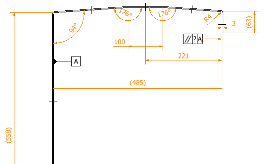
I'm designing a sheet metal part and when setting up the parallelism tolerances was asked a question on how much tolerances can the structure accept or how to calculate the accepted tolerance?

Adding a sheet metal structure for a reference.

Thank you in advance.
 
 https://files.engineering.com/getfile.aspx?folder=d4e843e3-6d83-4ad0-a005-bfbf78554a6b&file=tolerance.png
Replies continue below

Recommended for you

How much parallelism error you can afford for your design?
How far apart those two features can be out of their mutual parallelism and the part still function as intended?
 
This is usually an engineering stress problem, including how much force an assembler might be expected to apply to get the parts to fit.
tolerance_lo20im.png
 
If it's sheetmetal it's not so much the parallelism tolerance that is as much of a concern but the dimension between the to parallel flanges. It just depends on the accuracy of the bending process. If the shop is using CNC benders and they have a good grasp of the history of how the bends come out with that particular material, gauge, and bend radius they can tell you how much larger or wider the overlapping piece needs to be. It's better to be extra wider than a tiny bit narrower.
 
Restrained condition is a good tool that allows the designer to focus on the mating parts which usually are less bendy and more robust. With this, there's more allowance on the bent sheet metal because the tolerance applies at the "Restrained condition" aka the assembly level.
Just my two cents.
 
Why do you need a parallelism tolerance at all? Is there really a functional requirement in the assembly for these two surfaces to be tightly controlled for parallelism? Typically on thin sheet metal the default profile tolerance is acceptable because the part is flexible and will mate with its interfacing part once the fasteners are installed.
 
If too much force is required to force the edge down the metal edge will pop up between fasteners, creating a potentially hazardous condition.
 
Status
Not open for further replies.

Part and Inventory Search

Sponsor