Continue to Site

Eng-Tips is the largest engineering community on the Internet

Intelligent Work Forums for Engineering Professionals

  • Congratulations KootK on being selected by the Eng-Tips community for having the most helpful posts in the forums last week. Way to Go!

Steel Truss to Masonry Wall Connections 4

Status
Not open for further replies.

hdb35

Structural
Sep 18, 2023
4
Hello, I have several questions about a connection I am designing.

The building is a one story CMU (10m x 30m x 4.5m high) with steel roof trusses made from SHS Sections.

The steel trusses are modeled as simply supported, and the connection I am specifying is to weld the bottom truss chord to a base plate that sits on top of the masonry walls, and is connected by 2 - cast in plate headed anchor bolts. I am also specifying slotted connections on one side to simulate the "roller" connection. (See detail)

To design the anchor bolts for tension, I got the maximum uplift reaction at a single truss location subjected to components and cladding forces in a 3D model. This came out to around 22KN or 5 kips of uplift (each bolt is designed for 2.5kips in tension).

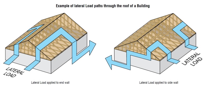
However, when designing the bolts for shear, I am unsure what forces to design the bolts for? This masonry building has designated "shear walls" at the four corners in both directions, so ideally I would think the a lateral wind load would travel through the roof diaphragm (the metal sheeting) and transfer to the shear walls. How do we account for this transfer or force?

In a 3D model with the MWFRS wind loads applied to the truss, I see a max lateral force at one connection as 30 KN, or 6.7 Kips - this would cause the anchor bolts to fail in shear considerably. I do not think in reality this much lateral force would be on the truss connections but instead most of it would transfer to the shear walls?

Also the end walls of the structure in the short direction are masonry gable walls - so any advice on how to connect the end purlins to these end walls would be appreciated as well to ensure a desired load path to shear walls? (Ie rake beam details or etc).

Again, I am not sure how lateral load is transferred from the roof diaphragm to the shear walls. If there is anything I am missing or misunderstanding here I would love to hear anyone's thoughts.
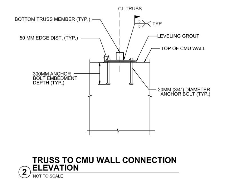
Connection_Detail_dyksnr.png
Lateral_load_path_d8bym1.jpg
 
Replies continue below

Recommended for you

You do not need or want a roller at one end of the truss - otherwise your CMU walls are not braced.

"In a 3D model with the MWFRS wind loads applied to the truss, I see a max lateral force at one connection as 30 KN, or 6.7 Kips - this would cause the anchor bolts to fail in shear considerably. I do not think in reality this much lateral force would be on the truss connections but instead most of it would transfer to the shear walls?"

This is why a simple structure like this should not be modeled in 3D. Easy enough to do by hand quickly. And if you can't do it by hand, you should not be using a 3D model.
 
Hi XR250,

Thanks for your response. In general, I am still concerned about the load path to the shear walls and how lateral force is distributed to the connections and the shear walls.

As you suggested, I did a quick and simple hand calc for two different scenarios in which I think the connections could take the lateral force.

Calc 1 assumes the connections take only wind on the roof itself.

Calc 2 assumes the force at the roof level is from the roof wind loads and the tributary wall wind loads.

As expected, Calc 2 is alot more conservative than calc 1, but based on diaphragm theory that I am familiar with, I would expect the roof sheeting to transfer this lateral load to the end struts (or gable walls in this case).

Either way, the results I get from either calculation show the roof anchor to fail in shear, and I am not sure if I'm thinking of this the right way.

There's a high change I have a fundamental misunderstanding of lateral load path, so any more enlightening comments would be helpful.

Thanks!

[URL unfurl="true"]https://res.cloudinary.com/engineering-com/image/upload/v1695080255/tips/Roof_Handcalc_e07hhb.pdf[/url]
 
If I'm understanding your Calc 1 correctly, you're making the assumption that the wind force on the roof (in the direction perpendicular to the ridge) will be transferred from the roof sheathing into the trusses and from the trusses into the top of the wall. If this is your assumption, I think it's incorrect. The wind load on the roof is normally resisted directly by the roof diaphragm, assuming that's the stiffest load path, which it almost certainly is. The roof diaphragm acts like a big beam with its supports at the gable ends.

In Calc 2, I agree that half of the wind load on the long wall will be transferred to the roof diaphragm, presumably through the truss support connection.

Half of your wind load in this scenario would need to be transferred from each end of the roof diaphragm, into the gable end truss, and from there, into the masonry end wall.

To attempt to answer your question about the shear force at the truss end connection, for wind normal to the ridge, there is a shear force perpendicular to the wall due to half the wind load on the wall, as discussed above. In addition, if the diaphragm chord forces are being resisted by the cmu wall, then there would also be a shear force parallel to the wall which somehow needs a connection. There would normally be blocking between the trusses along the top of the wall which would provide a direct load path from the roof sheathing to the top of the wall. This blocking would also provide a load path for wind forces in the direction parallel to the ridge, from the roof diaphragm to the long cmu walls.

I hope that helps. Let me know if I'm misunderstanding anything here.
 
Honestly, I think you need to study how buildings work. For wind perp. to the ridge, your diaphragm takes 1/2 of the wall wind pressure and all of the roof wind pressure. This is transferred into the gable end trusses as a shear. I would try to find some online videos and also start using a pencil and paper instead of MathCAD or whatever else you are doing your calcs on. It is unlikely that you have any bolt shear issues on this building.
 
Going off of ENG16080 - I agree with him that the roof diaphragm acts like a big beam with its supports at the gable ends. Those gable end trusses should be drag trusses that transfer the shear to those gable walls. Google "Drag Truss" and you'll get some good info.

I think a critical check would be to check if the diaphragm can handle the shear on that 30 metre span.

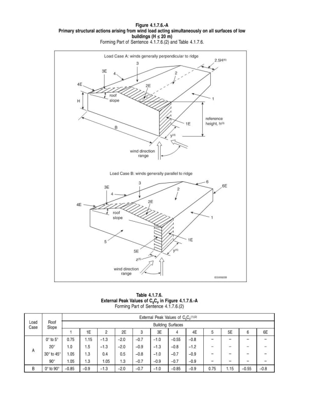
Also, I see your wind force is the same and acting in the same direction leeward and windward. In the NBCC (Canada) we have it so that in low pitches the forces are always uplifting on the roof and on higher pitches it is sucking on one side and blowing on the other. And leeward typically weaker than windward, see link. Maybe a second look at your forces can reduce the demand on the system.

NBCC_Wind_bnyyom.jpg
 
Thank you all for your helpful responses. From this discussion, I am in agreement that in theory, the roof diaphragm should transfer the force to the gable end walls. My main question now is how is this force transfer facilitated (ie through what connections?).

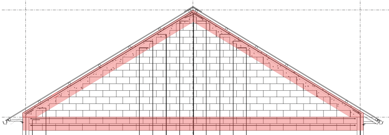
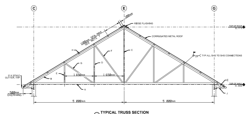
The end gable walls are masonry walls, not trusses (drawing shown previously was outdated). These would be my "Drag Trusses" (per Torchman's response). I agree that each of the 10m walls in the short direction will take half of the force at the roof diaphragm level (Vu), shown in my attached calc. At the gable wall, I plan to have the purlins from the last trusses framing into a rake beam (picture attached). How do I determine the reactions from each purlin onto the gable wall? Is it just the shear force (Vu)/# of purlins? What does this connection typically look like in a steel truss to masonry wall system?

Going back to the truss end connections - what is the shear force that the anchors are required to resist? If I understand Eng16080's response correctly, I solved for the max chord force in the roof diaphragm from the attached calc and distributed it among the number of trusses. This gives me a shear force of ~2.33 kips per bolt in the long direction of the building. The anchors would still fail via masonry breakout with this amount of force. Eng16080, you also mentioned using blocking along the top of the wall - would the steel purlin near this location act in a similar way or would you recommend adding an additional beam to connect the trusses on top of the wall?

I have been searching online for resources on lateral force paths for buildings, but haven't had much success with applying the theory to my situation - being how exactly the connections should be designed to ensure the system behaves according to diaphragm theory. I have seen much about wood truss connections, but little about steel. Links to any helpful readings/resources would be appreciated.

I'm following ASCE 7-16 provisions to do this design.


[URL unfurl="true"]https://res.cloudinary.com/engineering-com/image/upload/v1695135682/tips/Roof_Diaphragm_Forces_Calc_qt6fzk.pdf

[/url]
Gable_End_Wall_Elevation_zsewsc.png

Typical_Truss_Elevation_ywkmsx.png
 
hdb35 said:
I am also specifying slotted connections on one side to simulate the "roller" connection. (See detail)

That's is NOT necessary. The reason why we design trusses as pinned-roller is because that is (mostly likely) how they will behave and the difference between a pinned - pinned analysis vs a pinned roller analysis is HUGE.

When you have time, I suggest trying the following:
a) Create three identical trusses(hopefully in one file) that have identical loading, but the following boundary conditions: 1) pinned-pinned; 2) Pinned-Roller, 3)Pinned-Roller-with a longitudinal spring.

b) Obviously, when that longitudinal spring is set close to zero, you'll get behavior close to the pinned-roller model. And, when you have the spring set close to infinity (say 1E6 kips per inch) you'll get behavior like the pinned-pinned truss.

c) Now adjust that longitudinal spring to that of a cantilever column (3*E*I / L^3) of a standard story height. You'll find that results match VERY closely to the pinned-roller model. Now try to increase the stiffness by a factor of 10, or 100, or 1000 to see what kind of stiffness your column has to be to be closer to the pinned-pinned model. I suspect that you'll find it has to be very, very, VERY large. So large that you will never get even close.

d) I did some tests about this awhile ago. I came up with the result that the stiffness has to be something like 100 times larger than you'd normally have for that column (based on stress) for the pinned-roller model to have an error of about 10%. At 1000 larger, only then do the model results become closer to the pinned-pinned model.


hdb35 said:
At the gable wall, I plan to have the purlins from the last trusses framing into a rake beam (picture attached). How do I determine the reactions from each purlin onto the gable wall? Is it just the shear force (Vu)/# of purlins?
Essentially yes.

hdb35 said:
What does this connection typically look like in a steel truss to masonry wall system?
What are your purlins? There will be an eccentricity that wants to rotate your purlin between the deck and the location of the attachment. Many times blocking can be used.

hbd35 said:
The anchors would still fail via masonry breakout with this amount of force. Eng16080, you also mentioned using blocking along the top of the wall - would the steel purlin near this location act in a similar way or would you recommend adding an additional beam to connect the trusses on top of the wall?
Correct typically deck is fastened to the blocking and the blocking is fastened to the wall. What material is your roof deck?


Typically there should be blocking to provide a direct load path between the roof sheathing and the wall. For this type of construction, I would use the top course of the cmu wall (bond beam) to serve as the diaphragm chord. You would need to provide longitudinal rebar in the bond beam sufficient to resist the chord force (in tension). The chord forces would be transferred through this blocking and not through the truss end connection. If you were to do it that way instead (without blocking), I think you'd find that the shear forces at that connection are excessive. Perhaps you can use a purlin aligned over the wall to function as blocking assuming the purlin can somehow be connected to the wall.

The book "Design of Wood Structures" by Breyer provides a good description of diaphragm design. I know that your project doesn't use any wood, but the concepts are still applicable.

Also, be sure to check the unit shear capacity of your metal roof sheathing. Assuming that you're using steel deck, you should be able to get that value from the supplier. The capacity is a function of the steel deck profile, thickness, fastening, and support spacing.
 
All, it looks like the key component I was missing was the blocking and its effect in distributing the lateral forces from the chords to the shear walls. The end truss connections actually will not be experiencing the wind lateral load. Instead, I will design them for the seismic force in the short direction, which is presumably much less. The end purlins will be made continuous along the length of the building (via welded splices) and will be designed to take the axial load from the chord force of the diaphragm.

I will have blocking beams on top of the rake beam (in between purlins) where the roof sheeting is fastened and it will take the shear force from the diaphragm to the masonry wall.

I also won't be detailing one side of the trusses having slotted holes - both will have the same plate detail with normal sized holes.

JoshPlumSE - thanks for the practical example for explaining the pinned vs roller idealization and how an actual wall behaves in that fashion.

Thanks again all, your responses really helped my understanding of this structural system.
 
It may be easier to use a steel diaphragm chord - such as a bent plate or cont. purlin instead of forcing the load thru a bunch of blocking into the bond beam.
 
Status
Not open for further replies.

Part and Inventory Search

Sponsor