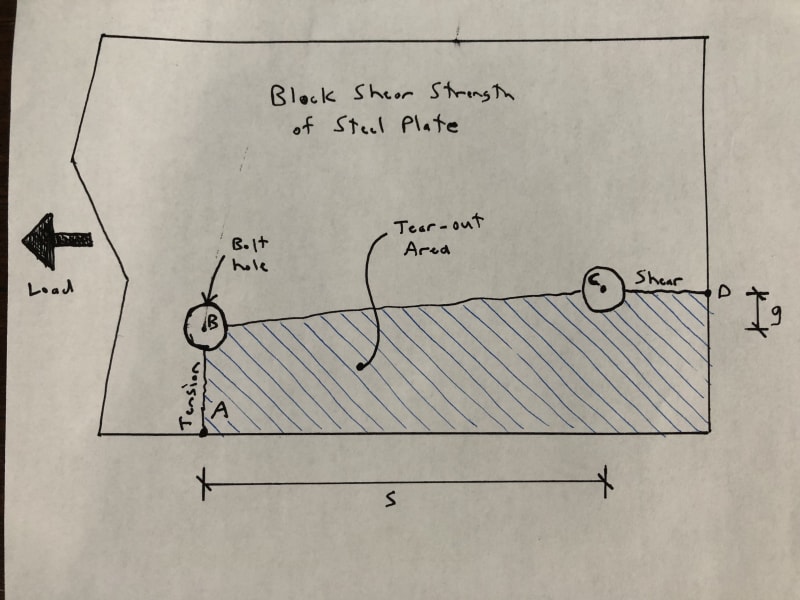
The AISC code gives equations to calculate tension rupture strength and shear rupture strength for failure surfaces perpendicular to and parallel to the direction of loading, but for a failure surface which is along a diagonal, it's not clear how the strength should be calculated. Refer to Segment B-C of the sketch below.

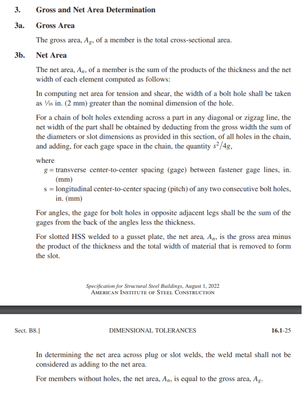
Section B4.3B of the code provides an equation to be used to adjust the net section area for tension in cases where there are staggered or diagonally separated bolt holes. Assuming a bolt diameter, H, and plate thickness, t, the net section area for Segment B-C according to the code is:
An = t*[g - (H + 1/16") + s*s/4g]
In cases, like the sketch, where the distance s is large in comparison to the distance g, the net section area calculated by the method above above seems unreasonable. Neglecting the deduction for the bolt holes, if the values s and g are taken as 10" and 1", then the length of segment B-C to be used in the area calculation is:
L = g + s*s/4g = 1 + 10*10/(4*1) = 26".
Geometrically, the length between points B and C is only 10.05", so using a length of 26" for any strength calculation seems wrong.
Concerning the s*s/4g term in the equation above, I looked into this a bit further and found a paper from 1922 describing how it's derived (see attachment). Back then, the term was used as a deduction (not an addition as used in the current code) which included the bolt hole area. It seems that per current usage, this term should not be taken greater than the deduction for the bolt hole. On page 2 of the paper, you'll see that the deduction is never taken less than zero.
If this logic is sound, then per the equation for An above, the s*s/4g value is limited to (H + 1/16") and the equation reduces to:
An = t*[g - (H + 1/16") + (H + 1/16")] - t*g.
This seems more reasonable, but still not quite right. As the value g approaches zero, so does An. For a tiny value of g, An and the tension strength is nearly zero. Once the value g is exactly zero, the segment B-C is parallel to the loading direction, and the strength is based on shear rupture rather than tension. For a segment which is nearly but not quite parallel (like in the sketch), it seems reasonable that the shear strength more accurately predicts the capacity.
A couple questions for anybody still reading:
[ol 1]
[li]Do you agree that the s*s/4g value used in the code for staggered/diagonal holes is inaccurate for conditions like above, or am I missing something?[/li]
[li]Does the following approach seem reasonable in terms of estimating the capacity of a sloped segment? Capacity equals the maximum of:
[ol a]
[li]the tension capacity with s*s/4g limited to the hole diameter, and[/li]
[li]the shear capacity calculated along length s[/li]
[/ol][/li]
[/ol]
A previous thread by phamENG is somewhat related, although I wasn't able to draw any conclusions from it: Link

