Eng-Tips is the largest engineering community on the Internet

Intelligent Work Forums for Engineering Professionals

Raised Rafter (rafter tie) analysis

Status
Not open for further replies.
Replies continue below

Recommended for you

Not sure if this helps. This is from a response to a post a couple months ago:
FBD_nfdvep.jpg

The equation at the bottom for Fx gives the outward thrust. This is obviously much simpler than the spreadsheet that you linked above, but it could be the starting point for creating something similar.
 
lexpatrie said:
Anybody know if that hand sketch posted matches the published result in the Journal of Light Construction, Truesdale, October 2008?
If you mean the sketch above that I created, then yes, it should arrive at the same reaction as the article. If not, let me know, as I'll need to give my stamp back :)

The article uses different definitions for it's variables than I do. I like to call length, L, the full roof width, whereas they use half the width. Also, the height of the tie, h, in my case is measured from the bottom of the rafter, not the top, which I find more logical as most builders/architects generally describe the tie location relative to the bottom.

The information in the article is good, but I would add a few additional comments, which might be applicable depending on how particular you are. In designing the connection between the tie and the rafter, I would use NDS to determine the allowable nail capacity, rather than base it on 100 lbs for a 16d nail. Based on another thread living here somewhere, some engineers were lamenting how most framers found out in the wild are using nail guns with 0.120" diameter nails, which are a fair amount weaker in shear than a 16d common nail. Be sure to account for that if it's relevant in your case. Also, if the roof is loaded with snow, you can take advantage of a higher load duration factor, CD, which will give a little extra capacity. Although NDS doesn't require any minimum nail spacings or edge/end distances, using the recommended distances found in the Commentary, Table C12.1.6.6 is probably wise.
 
XR250 said:
Unless this is simply a fun and useful exercise for you, why not simply use a 2-d modelling program?
Not sure who this question is meant for, but I use the thrust calculation above as a quick sanity check. Sometimes I'll run a 2D truss/frame analysis through RISA (or whatever) for stuff like this. The thrust calc. provides a double check of the software output. It's especially helpful if I'm checking somebody else's work. I've found that even simple 2D layouts like this are often modeled incorrectly in software, like with pin supports being used for both rafter ends.
 
I did go the RISA 2D route, it was painful. Beyond painful. I haven't done RISA in like six years and even then, with the notes i had. Not that it didn't give results, but there were so many intricacies to nail down it took nigh forever. The tie reaction was wrong, etc. etc. etc. Touch one setting and the whole model tanks with some instability error you can't find.

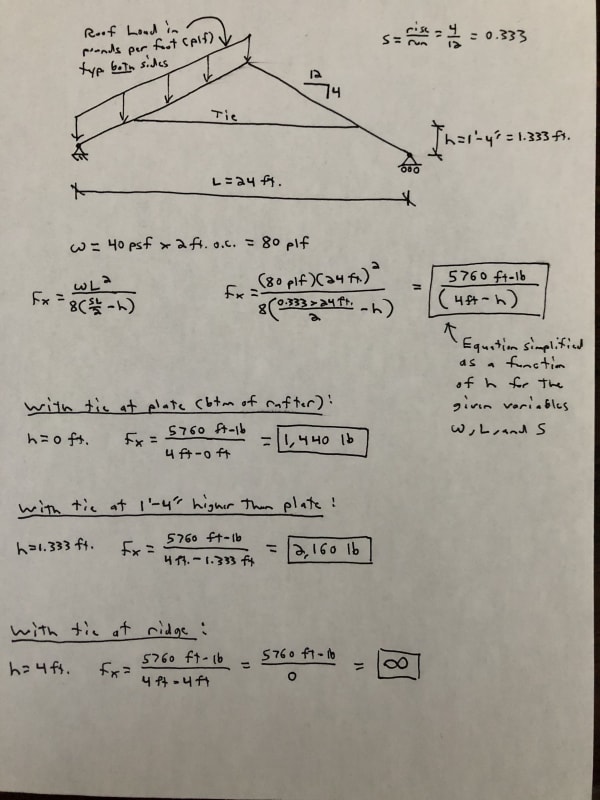
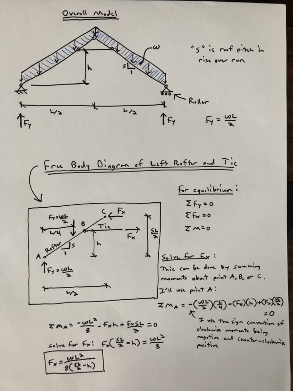
The tie reaction can be obtained by statics, which I did once, didn't like the formula I got, started rooting around and found the Truesdale. I haven't managed to get Truesdale and Eng16080 formulas to match yet but I didn't try too hard yet. I know the variables aren't identical, and even Truesdale seems to have junk in the formula versus normal variables (rise/run I'm looking at you).

The RISA difficulties I had started with load being too high (projected versus global Y, I guess, or some other default. I took notes in my Excel spreadsheet so I can learn from this one), so the tie force was 70% too large, I suspect given the flexibility of the framing there's second order effects a static analysis won't capture, and then it started getting into the more esoteric, with custom species for 1900s wood, custom shapes (rough sawn), and then all the weird variables dealing with unbraced lengths. It took a long time to even verify the allowable stresses RISA was shooting out, because so much of the factors are hidden with checkboxes and whatnot I had to find them. (Repetitive stress, I'm looking at you). I have a spreadsheet of my own, adapted from a previous project that wasn't nearly as goofy that could be done via hand calculation, (lower pitch though but at least the rafters and ceiling joists could meet prescriptive current code for current snow loads), collar ties, I think, or I added those, but the purlin braces were down to the ceiling joist, not the interior wall. So I was trying to get it to work and/or verify RISA.

Mine is a building that's survived for about 100 years as it was built, but it doesn't math out very well. It's one of those projects that starts, goes dormant, starts again.... I know we (Eng-tips) get into these perennial conversations about raised rafters/collar ties, over and over. Every conversation seems to start from zero, also. We're on the second building official now, also. The first one moved on.

It's a long story.
 
lexpatrie,

From my experience, RISA 2D/3D is a powerful and very useful program, although I definitely feel your pain in getting the model correct. One incorrect input or assumption can lead to the results being way off. As a general rule, I don't fully trust anything coming out of it without verification by some other method. That goes for any other software to be fair, as well as for my own manual calculations. For something like this simple truss, I'll spend as much time as necessary to verify the output from RISA. Once I'm finally confident that the output is valid, I'll save the file for future use as a template of sorts. So, rather than start from scratch next time there's a truss with similar characteristics, I'll start with a copy of the truss that I verified, and I'll modify it.

With that said, often the best ways are the most simple. If the Truesdale article you linked above gives a reasonable answer that you trust, that's worth a lot.

Concerning the example calculations in that article, by using the equation I derived, you should arrive at the same results for horizontal thrust. Really, both methods are essentially the same. See below:

Truesdell_Calcs_rgiaqq.jpg
 
Decent looking output. RISA always takes so much tweaking and can't superimpose Moment/shear that I know of.

I saw another post along the same subject mention FTool.
 
I use Risa-3D and like it a lot, but it definitely takes time to get used to any software. Risa sign convention is also opposite of traditional. In Risa, compression is (+) and tension is (-). Bending moment is drawn on the tension side, too.

Here's an attachment of the same frame I checked in Strian, but this time in Risa-3D. Values are kind of hard to read. Feel free to ask questions about Risa. I'm sure anyone would be willing to help, myself included. I'm no expert, but I'm at least somewhat comfortable with it.

Nice to know about FTool! I bookmarked that
 
 https://files.engineering.com/getfile.aspx?folder=e6f14ab8-5e31-4e34-b65d-978eb00a9447&file=risa-3d_rafters.pdf
You are way better at RISA output than me. I just screenshot output that's moderately decent, though I'm surprised you can do an end release of both elements at the ridge and not get a stability/matrix fail. I only released one end, it never occurred to me to release both because I thought it would bomb out. Or does it get that "we added a spring" message?
 
All I did was copy/paste some screen snips into bluebeam and mark it up a bit.

I think the trick is only releasing "Mz" (strong axis bending) at the ridge (and at the tie ends). I didn't have any issues or warnings/added springs when I did that. If I tried to release additional things, then it probably wouldn't be happy. Also, the ridge support is one reaction in the x-direction only. The eave supports are one reaction in the y-direction only. I believe that's the right way of modeling it, but someone can correct me if I'm wrong. I don't practice in residential.
 
Yeah you'd want one support to be a horizontal slider, the other fixed, that keeps the rafter tail from getting horizontal reactions so you get the correct force in the rafter tie / ceiling joist.
 
RattlinBog, I've always modeled the joint between the rafters as a pin, not a horizontal reaction, but with that said, your results look correct.
I don't currently have a version of RISA to mess around with, but to model this, I would:
[ol 1]
[li]Add a pin reaction at the left side, roller at the right[/li]
[li]Model all joints pinned, except the joints at the supports which are fixed (otherwise the model is unstable with there being a pinned joint at the end also with a pinned support)[/li]
[li]I forget the particulars now, but you also want to release torsion from the members. Otherwise the model is unstable. The tie member, for example, can spin about it's longitudinal axis if this isn't accounted for.[/li]
[/ol]
 
I did a comparison with one rafter end pinned (x & y fixed) and the other on a roller (only y fixed)--attached. No reaction at ridge. Only difference seems to be the deflected shape, which is what I was expecting; internal forces are the same.

I'm releasing Mz (strong axis bending) at the ridge and at each end of tie so they don't take moment. Is that still correct? I'm assuming the apex/ridge is typically constructed with no moment resistance, and also assuming the tie is axial-only. If I don't release Mz, then you'll get moment at the ridge connection, and you'll get some small internal moment in the tie.
 
 https://files.engineering.com/getfile.aspx?folder=1b3abf63-7daf-4ad1-a824-3e77f6a5b21b&file=rafter_comparison.pdf
Status
Not open for further replies.
Back
Top