Eng-Tips is the largest engineering community on the Internet

Intelligent Work Forums for Engineering Professionals

  • Congratulations waross on being selected by the Eng-Tips community for having the most helpful posts in the forums last week. Way to Go!

Cylindrical feature primary with surface secondary, what is the point?

Status
Not open for further replies.

Diametrix

Aerospace
Jan 31, 2023
50
US
One thing I'm still struggling to understand is what is the difference between specifying a single cylindrical feature datum for true position tolerance or the same with a flat perpendicular surface used as the secondary datum when no material boundary modifiers are used. Here is an example from the standard:

UAME_ijsfoi.jpg


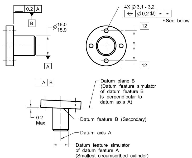
Here we have true position tolerance zones for the four holes as four cylinders which axes are basically located and parallel to the datum axis A which is the axis of a smallest circumscribed cylinder that is touching the datum feature B. I guess my problem in understanding is right here - why is it important that it is making contact with the datum feature B? If we remove datum B completely from the FCF and have only datum A referenced, wouldn't we end up with exactly the same size and orientation for the tolerance zones for those holes?
 
Replies continue below

Recommended for you

One reason could be to set up an A|B datum system that will also be used in other callouts on the same drawing. With the exact same datum references, the simultaneous requirements rule would then apply.
 
Diametrix,

I agree with Garland23. Imagine the pin from the figure has, for example, a radial hole that is going thru the datum feature A and is controlled with a position tolerance wrt A|B. The two position FCFs - for the pattern of 4 holes and for the radial hole - will then have to be considered simultaneous requirements effectively creating a new pattern of 5 features controlled not only to the specified datums but also circumferentially to each other.

But you are right - as a stand-alone control, B in the position tolerance to A|B adds little (no?) value.
 
Thank you for the replies! Talk about fine print. So in the case you are describing the only reason to have datum B in the FCF as a secondary datum is because it is used to basically locate this new radial hole from datum B, right? If the hole were in the pin but an axial one, then you could've used a single primary datum A for both FCF's and still have simultaneous requirement applied to both?
 
This is part of an example to show the difference in expected orientation and "size" of the datum feature simulators based on the order of datum feature references. In this portion of the example, the inclusion of has no obvious function; it is only there to establish the contrast with the other cases.
 
The contrast could have as well been achieved, but without any controversy, by simply using a radial hole as toleranced feature and not the axial pattern.

If I recall correctly, the figure and related issues were discussed in the forum before.
 
Status
Not open for further replies.

Part and Inventory Search

Sponsor

Back
Top