Continue to Site

Eng-Tips is the largest engineering community on the Internet

Intelligent Work Forums for Engineering Professionals

  • Congratulations KootK on being selected by the Eng-Tips community for having the most helpful posts in the forums last week. Way to Go!

I have this weather station pole th

Status
Not open for further replies.

Juan15

Student
Oct 10, 2023
3
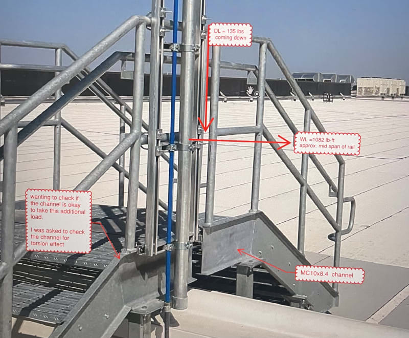
I have this weather station pole that has been attached to an existing railing/stair. The railing and stringer were not initially designed to support this weather station pole. The (wind)
IMG_4364_pdoyrp.jpg
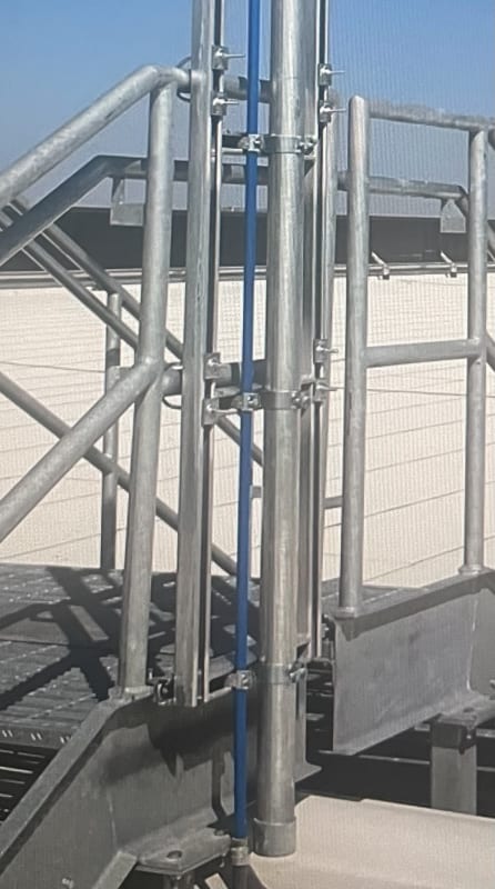
moment produce by the post on the railing at mid span is approximately 1082 pound per feet and the total dead load coming down from the pool is 135 pounds. I am wanting to check the existing stringer capacity for this added moment and load. I am aware that this is a couple moment of some sort and it’s creating it torsional effect on the Stringer. How would I go about checking the stringer. It’s a MC10x8.4
IMG_4364_vewufv.jpg
 
Replies continue below

Recommended for you

I can see a "heavy" fitting at the base, but nothing at the top flange of the base steel beam.

by "stringer" do you mean the vertical stiffeners (that look to be supported by the handrail ?

If so I think you've got a more complicated loading than you think. I'd divide the wing load between the 6 supports (5 supports to the vertical members and one at the base).
Then these vertical members are supported at 3 locations (on the hand rail).

This is a simplistic approach. A more thorough approach would have the vertical members and the pole all bending together, which sounds like a more complex solution.

"Hoffen wir mal, dass alles gut geht !"
General Paulus, Nov 1942, outside Stalingrad after the launch of Operation Uranus.
 
I was asked figure the couple moment the pole would produce at the mid span of the railing and then to check the bottom steel for a torsion affect. Is there some type of equation in the aisc that I follow. I couldn’t find much for channel shapes
IMG_4365_uaqcsn.jpg
 
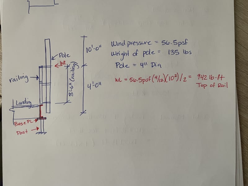
well, the wind load acts a lot higher than you've drawn, closer to the top of the hand rail.

And this is reacted over the two attachments to the flanges of the MC10x8.4 beam ... can you do that ? a simply supported beam ?

I'd take the dead load out on the bottom fitting.

"Hoffen wir mal, dass alles gut geht !"
General Paulus, Nov 1942, outside Stalingrad after the launch of Operation Uranus.
 
So I’be calculated the wind moment produced at the top of rail by the pole
IMG_4366_mdndrm.jpg
 
why would the wind load only act on the upper part ?

ok, you don't really need the moment at the top of the hand rail. It makes sense to determine the wind load and where it acts. Then you have to solve the simply supported beam with and overhang load. First is basic strength of materials. Can you do this, and get the loads on the two supports of the beam ?

take moments about the lower support ... moment of the wind load (which is not the moment at the upper hand rail) is reacted by the moment due to the upper support ... it'll look something like Wind_load*9ft = upper_reaction*10in/12

"Hoffen wir mal, dass alles gut geht !"
General Paulus, Nov 1942, outside Stalingrad after the launch of Operation Uranus.
 
Was the wind pressure given, or was it part of the problem to be solved? If you calculated it, did you account for the drag coefficient on a cylindrical surface?

As far as the torsional moment on the channel, if you're allowed to ignore the contribution of the portion of the handrail where it's sloped, then it becomes a fairly simple analysis, because whatever forces are applied at the connections to the handrail, ultimately are resisted by torsional strength of the channel.
 
Status
Not open for further replies.

Part and Inventory Search

Sponsor