Eng-Tips is the largest engineering community on the Internet

Intelligent Work Forums for Engineering Professionals

  • Congratulations waross on being selected by the Tek-Tips community for having the most helpful posts in the forums last week. Way to Go!

Drag Strut Preferred Detail

Status
Not open for further replies.

Brad805

Structural
Oct 26, 2010
1,485
0
36
CA
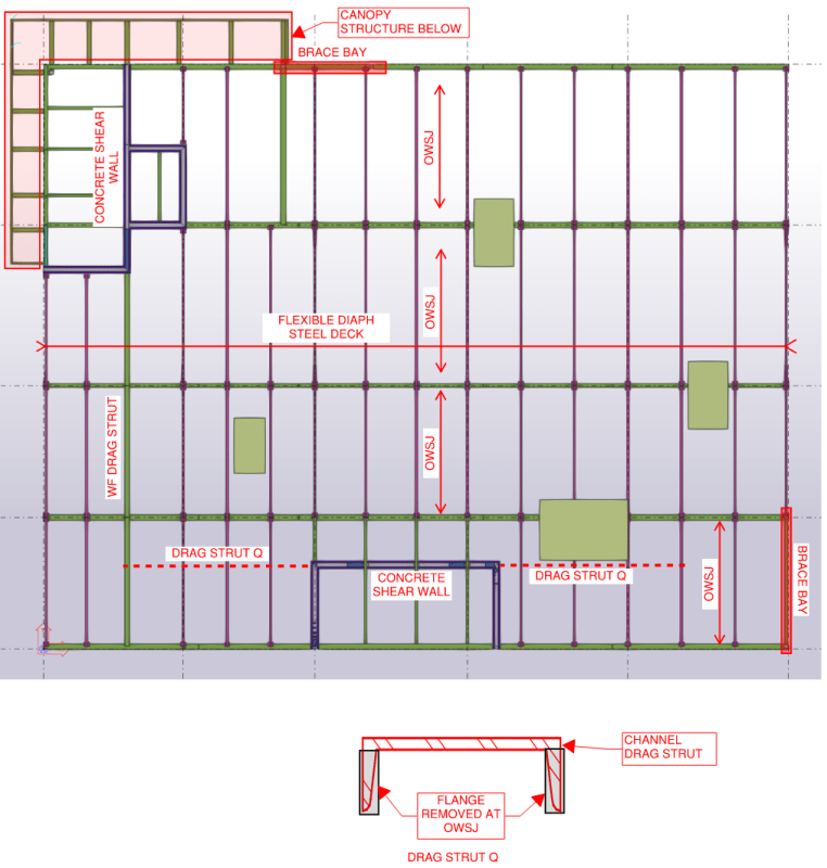
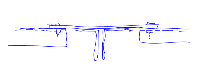
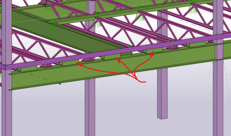
I have a small two storey bldg I am working on. The roof diaphragm is a flexible steel deck over OWSJ as you can see in the image below. My question relates to the one drag strut. I have seen a channel section used commonly for this purpose. The flanges are cut out at the OWSJ and it is welded to the OWSJ top chords. I have seen it in the field and I am not a fan of the effect it has on the decking in this area. What are others doing here?

DRAG_STRUT_Q_fleiys.png
 
Replies continue below

Recommended for you

You can't go through the top flange of the joists as there is that pesky little gap between the two angles. I suppose you could fill that gap in with some welding but that seems improper, expensive, overboard and a possible invalidation of the joist manufacturer's warranties, etc.

The channel idea, to me, is a good one. Yes you get a slight hump in the decking but any other type of drag strut detail will involve some type of plate/steel entity extending over the top of the joists.


Can you use a 6" channel, flip it and hope they can finagle the deck ribs over the legs?
You could also use a wide flat plate and reinforce it with the channel toe down. Then weld the deck to the plate (interrupted by the channel)
 
I've always done it where the drag struts act in tension only and just used a flat plate. Yes it means longer drag struts to get the fastening, but it simplifies the construction aspect of it.

That being said, I practice in a non-seismic area. So YMMV
 
Thank you. This bldg is not in a high seismic zone, but my review eng always asks about these things. I think I will use the channel with the flanges removed at the joists. It is not complicated to make and I get 3D models from Canam nowadays so we know the actual width of the top chord before they need to fabricate now. Flipping the channel up is a good idea, but would undoubtedly cause a problem since that will likely be two different trades.
 
1) I do the coped channels and have seen that in a lot of BC work that I've reviewed.

2) For common deck profiles with 6" flute spacing, I find that it takes an 8" channel to not have issues with not having overlap between the deck troughs and the channels.

3) JAE's point about not being able to pass axial across a pair of joist TC is a salient one. Solutions:

a) Some folks do a patch plate connecting the channels. That tends to make a stack of plates at the TC which is well in excess of 5/16".

b) I haven't tried it yet but have been envisioning something like the detail shown below. The bolts would be removed after the welds are made. I anticipate pushback, groaning, and eye rolling. Note that the channels and patch plate need to be sort of moment connected in order to keep the whole thing from folding up like an accordion. One also does not love welding transversely to the chord of a joist carrying truss dead load. Maybe a screw connection would be worked out or something. Obviously, in compression, the joist is bracing the strut.

c01_tc9hga.png
 
Brad805,
I'm guessing there's a good reason for the beam layout shown, but I'll ask anyway. Why not place your beams in line with the shear wall and use the beams as the drag strut?
 
clliff234 - that might work. I'd be worried that the joist diagonals might follow Murphy's law and be in the way.

 
Eng, the arch set the grids long ago before I got started. I could have added another brace bay in the exterior wall, but I liked the idea of using the concrete wall since they have many windows.

Cliff, that is a good idea. I could spec the joist supplier coordinate cross bracing for the drag strut. I am sure they can address the problem of dragging the force across their top chords.

Thanks again.
 
What, K series or LH? (It's coming back to theaters Dec 3 and 6.)

The standard seat is 2 1/2" for the K series and 5" for LH.

The joists themselves have some demonstrable rollover resistance, see the Vulcraft "Designing with Steel joists" 3rd edition, Chapter 7, and the "customary" detail that is shown in the Vulcraft book is a tube steel section (HSS). You have to kind of adapt this into whatever you have beneath the joists, but I suppose with a lateral system in one spot only along the whole side of the building it's a steel frame under it, then the drag strut is the steel beam supporting the joist. Path through any interrupting columns, etc, but you have a longer distance to get the load out of the diaphragm and through into the braced/moment frame in one bay you depict.

Regards,
Brian


We will be using Canam joists with 4" seats. Given the spans in this case I expect something like a double L2x2x3/16" or so for the top chords. We can get Vulcraft, but they are not usually competitive in our area. The typical seat data from Canam is below. Generally, most in Canada provide alternate means for these type of details. RFI's can go a bit mad if you stray from their standard details.

CanamSeat_pq87cr.png
 
I haven't had a need for this type of drag strut away from a beam line, but I'll throw out this idea for consideration. Basically jayrod12's plate beefed up with a tube that can fit in the low flute. This would be constructed above the deck with no welding required (except at the strut ends probably). I don't necessarily see a need to weld the strut to the joists, since the deck is already fastened to the joists and the strut is fastened to the deck.

Screenshot_2023-10-19_114020_hizkg2.png
 
Since the advice has been so helpful, I thought I would add one more detail. Given the parameters for the joist seats another detail that seems to come up is how to transfer the lateral load from the chord into the WF and ultimately to whatever brace you need. A detail we have used that is not overly popular is to add a short HSS segment midway btw joists. This is stich welded to the WF and the chord is shot down to it by the decking trade. We use an HSS to make it easy for the steel fabricator to install it. Any better ideas?

TransferElement_v6wjre.png
 
I think the short HSS segments is a pretty universal detail, but following the philosophy of minimizing welding, perhaps replace the HSS with a bent Z-shape plate or heavy gauge sheet. That way it could be screwed or PAF'd to the beam and chord. Especially so if both the chord and Z-plate are gauge steel members. I've been leaning more into that type of PEMB-style use of CFS secondary members lately, since most structures I've been working on recently do not require hot-rolled secondary members in most cases. Makes things easier and cheaper.
 
Brad805 said:
We use an HSS to make it easy for the steel fabricator to install it. Any better ideas?
I'm not sure it's necessarily a better idea, but I've used channel sections with legs turned down for K-series joists. Easy fillet welds on both sides to the beam top flange. MC4x13.8 and MC6x12 are two good options for K-series. This probably doesn't work as well, though, for a deeper joist seat.
 
Brad805 said:
Any better ideas?

I, also, most commonly see the HSS detail. That said, I also very commonly see at every second joist space rather than every one. Logically, this should make your detail half as despised as it would be when you hit every joist spacing.
 
bones206 said:
I haven't had a need for this type of drag strut away from a beam line, but I'll throw out this idea for consideration.

I don't love it. I think this is a case of "if it were that easy, we'd already be doing it this way". Issues that I see:

1) How do you splice the HSS when you inevitably need to?

2) How do you connect the HSS to the braced frame beam or whatever below? This, particularly given that one usually is not able to exert control over the locations of the deck flutes in plan.

bones206 said:
I don't necessarily see a need to weld the strut to the joists, since the deck is already fastened to the joists and the strut is fastened to the deck.

3) These struts can have loads in them in the 20kip+ range at times. I would not feel good about relying on the pullout capacity of a few deck screws performing the bracing function for loads of that sort.

 
Status
Not open for further replies.
Back
Top