Flat Square Parallel
Mechanical
Hello guys!
Long-time lurker here but first-time poster. Engineer designing steel structures but have less experience with concrete design.
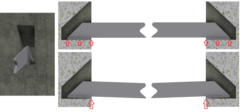
We have an application where a steel structure will be supported via four extending arms that are sitting in pockets made into the side of a fairly green (~1ksi) concrete wall. See the attached image below. The arms are solely transferring a vertical load to the pockets. The concrete wall is 12" cast against rock, and extends left/right/below of the pocket by more than 10'. Concrete is not reinforced.
I need to make sure that I don't exceed the bearing capacity of the concrete in those pockets. If I understand correctly, this would be straightforward if we considered that the arm bearing plate was lying flat against the pocket : it's a matter of making sure the average contact pressure does not exceed the allowable concrete compressive capacity (right?). But considering that there will be flexure in my structure, as shown in the image (where the deformation is very exaggerated), then the actual load transfer will happen at the edge of the pocket. I mean, the tip of the arm might lift by 0.002-0.003" or the like - imperceptible - but an FEA of this clearly shows that the load is transferring at the edge. Do I need to account for this localized high-stress point, or am I overthinking it, with concrete? I know that ideally, the arm would have some kind of swivel between the arm and the bearing plate, but the equipment is existing and new arms cannot be made easily.
Also, would there be other load cases that one would need to consider other than bearing capacity?
Thanks!
FSP


