Continue to Site

Eng-Tips is the largest engineering community on the Internet

Intelligent Work Forums for Engineering Professionals

  • Congratulations KootK on being selected by the Eng-Tips community for having the most helpful posts in the forums last week. Way to Go!

Stress at corner in 90 deg frame

Status
Not open for further replies.

SpaceEngineer4

Aerospace
Aug 8, 2023
12
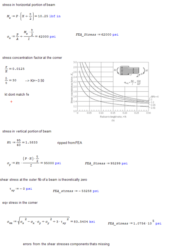
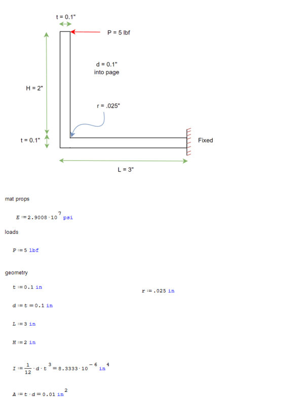
Good morning lads and salutations. i have clarifications to give on a post i made in another forum here in the structures forum. i am designing a single piece bent frame for an aircraft ground support structure (pics are simplification of actual design, assume uniform depth into sheet w rectangular section) and have made discovery that the fe stress does not agree well with the hand calculations. interesting couple notes:

[ul]
[li]the shear stress in the corner is nonzero, despite the traditional beam theory stating that shear on outer fiber must be zero - these change the eqv stress est and yield criterion [/li]
[li]the stress concentration factor is not easily read from the tables [/li]
[/ul]

is it really true that for such a simple structure detailed fe is required to perform the design? you can view that from the calcs, the values match detailed fe for most nominal bending stress, but not the concentration and not the shear stress. any one have insight why, or sugestions to improve the calcs? what are the design recommendations here? i need to design for strength and fatigue so getting local and nom stresses are important.
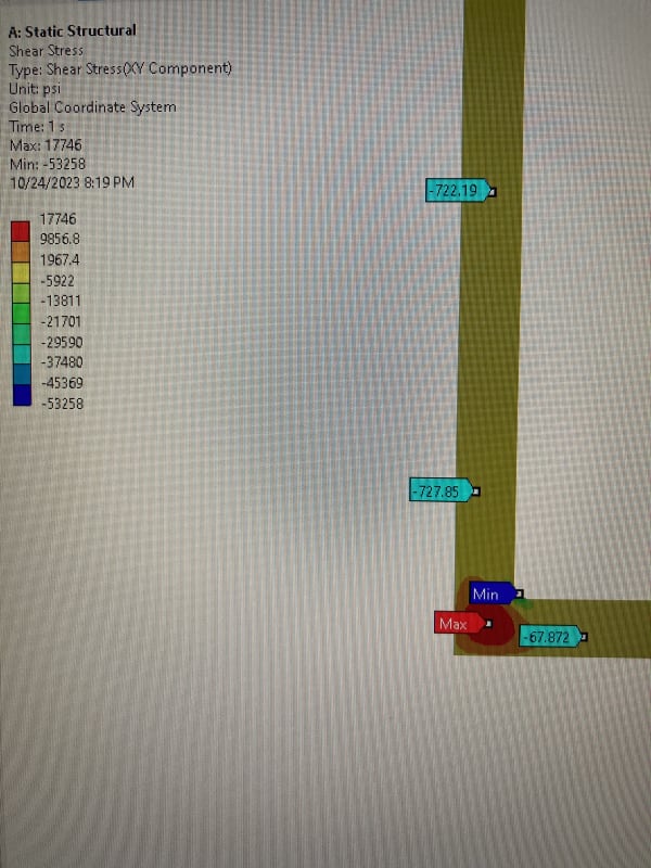
IMG_2389_p26wod.jpg
frame_calc_1_dghnrd.png
frame_calc_2_fnpodf.png


Sincerest gratitude to all in advance.
~Robert
 
Replies continue below

Recommended for you

Why not just add a small gusset plate in the corner and be done with it?

I think the issue with the shear stress at the corner is that right at the corner there is no “free surface” so the simple beam shear calc does not apply.
 
"have made discovery that the fe stress does not agree well with the hand calculations" ...

seriously ? that's your discovery ??

FE can shine a light on things that hand calcs gloss over, depending on the rigor of the FEA and the detail of the hand calc.

Most of the time hand calcs simplify the situation, hopefully conservatively, so that a simple calc shows the structure good.

I wouldn't lose any sleep over it !

"Hoffen wir mal, dass alles gut geht !"
General Paulus, Nov 1942, outside Stalingrad after the launch of Operation Uranus.
 
rb1957 said:
seriously ? that's your discovery ??

i understand that hand calculations are simplified, but my question goes toward if hand calculations are off the detailed model by almost 25% even in the simplest of cases, how can one even begin to assess a structure without the use of detailed fea for "real" structures without gigantic factors of safety? think of complex shapes, short beams and the like which dont fit the usual assumptions. before fea was around, it seems that stress calcs couldn't have been better than an order of magnitude check on real structures. and in fatigue applications it has to be worse yet on real structures. i suppose this is the value in testing... but stress analysis up front couldnt have been very accurate. and i dont think aircraft industry used "large" safety factors either (>5).
 
the airplane industry is "proof" that hand calcs and experience can produce an efficient structure without large safety factors.

the quotes are because we still get tripped up either by things we didn't see/anticipate or by things we saw but dis-believed.

"Hoffen wir mal, dass alles gut geht !"
General Paulus, Nov 1942, outside Stalingrad after the launch of Operation Uranus.
 
The kt case you’ve used doesn’t reflect your geometry and loading. I had a quick look at Roark (7th edition), it’s not as comprehensive as Peterson but for a quick estimate, case 22 (square or filleted corner in tension, page 793), although doesn’t fit the geometry ratios completely and the loading is different, it gives a kt of 1.88. I would suggest looking for a more representative geometry and loading kt case.
In addition, the beam at the corner may be acting more like a non-prismatic beam, where max shear can be seen at the outer surface, going against prismatic beam theory.
 
In the old days we used proven design concepts to try to avoid stress concentrations.
Though “proven” was often the result of lab testing or in service problems. A lot of the fatigue methods and data and design guides we have now were the result of fatigue cracking in service, usually but not always detected before catastrophic failure.
For the angle frame, we would have just added a gusset plate on one or both sides at the corner and not worried about it.
But we are so much “smarter” now with FEA, we routinely dump thousands of silly load cases into the FEM because we can, rather than actually thinking about what loads actually size the structure. Sigh.
 
Status
Not open for further replies.

Part and Inventory Search

Sponsor