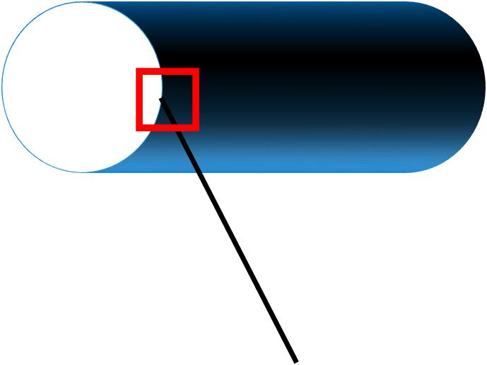
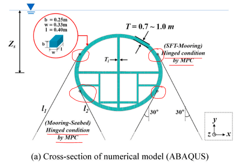
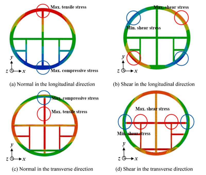
Dear experts, I would like to ask how to constrain the contact between the truss unit and the surface of the cylinder shell in ABAQUS in a reasonable way? I tried to use a mpc pin connection between the endpoints of the truss unit and a bit of the shell unit, but this results in a large stress concentration, which is not what I want. If I use the endpoints of the truss to connect to the surface of the shell at multiple points, the center of the piece will become rigid and all the stresses will be 0, which is not what I want. I would like to ask you experts if there is a good solution for this?
Navigation
Install the app
How to install the app on iOS
Follow along with the video below to see how to install our site as a web app on your home screen.
Note: This feature may not be available in some browsers.
More options
Style variation
-
Congratulations MintJulep on being selected by the Eng-Tips community for having the most helpful posts in the forums last week. Way to Go!
You are using an out of date browser. It may not display this or other websites correctly.
You should upgrade or use an alternative browser.
You should upgrade or use an alternative browser.
Connection of ABAQUS trusses to surfaces or sections of cylindrical shells
- Thread starter a126z
- Start date
- Status
- Not open for further replies.
There are of course many ways to do this (attach a truss (1D elements) to a cylinder (2D elements)
1) how finely meshed is the cylinder ?
2) how are you attaching them in the real world ? I suspect a lug with a bolt, or some such.
The easiest way is to project the truss element onto the shell and have a common node. A key to this is also respecting the real world attachment freedoms/stiffnesses. If you've modelled the truss with beam elements and the shell with plates, then you will need to release some of the bending freedoms (that don't exist in the real world). But this will, as I think you've already done, give you high localised stresses. To which you say "these stresses are not real, they are an artifice of the FEM" and do a hand calc (to pass the truss load across the bolt, into the lug, and from the lug into the shell (locally). But then this sounds like "I tried to use a mpc pin connection between the endpoints of the truss unit and a bit of the shell unit, but this results in a large stress concentration, which is not what I want", so maybe you've done this without resolving the fictitious high stresses ?
If you large large elements in the shell, you can do mesh refinement at the connections, to localise the high stresses to something within your lug.
And this leads to the next idea. Model the lug. I don't like this approach, I see it as a waste of computer resources (and one day the machines will rise up and extract a price for this). I see this as an extension of the common belief that FEMs are Right, and a reluctance to say "I can solve this problem with math".
Another thing you can do is to use a stiffness element (NASTRAN have CBUSH elements, I'm sure ABAQUS has something similar) to add an artificial stiffness/flexibility between the truss and the shell
"Hoffen wir mal, dass alles gut geht !"
General Paulus, Nov 1942, outside Stalingrad after the launch of Operation Uranus.
- Thread starter
- #4
I've tried using bindings and so on. But you still have the problem that you had before, if you have a one-to-one connection, you have a stress concentration, if you have a one-to-many connection, you have a rigid area. Is there any way to connect the end points of the line to the surface without using connectors? And there's no stress concentration, no rigid body. Is my connection area selected incorrectly


you know there are two type of rigid element (well, there are in NASTRAN). One (RBE3, I think) has no stiffness, I think it proportions the load by relative stiffness (between the dependent (independent?) nodes). The other (RBE2?) forces the geometry (of the dependent/independent nodes) to remain the same (infinite stiffness).
I (again) suggest a single node (where the truss penetrates the shell), and take the loads from teh model and do a hand calc.
@nd would be mesh refinement around the penetration, and model the fitting.
"Hoffen wir mal, dass alles gut geht !"
General Paulus, Nov 1942, outside Stalingrad after the launch of Operation Uranus.
a126z said:if you have a one-to-one connection, you have a stress concentration, if you have a one-to-many connection, you have a rigid area
Not necessarily rigid if you use coupling constraint. But all such connections will introduce some spurious effects. This is a highly simplified model of the connection after all. You would have to model it in a more realistic way (like it's supposed to be connected in real life) to get accurate results for the connection itself. Otherwise, this can pretty much only serve as a simple representation of the connection for a larger model in which there's a different region of interest.
- Thread starter
- #7
- Thread starter
- #9
This article uses beams element and the solid element to connect. The connection between them in the article is an mpc pin. Only the displacement degrees of freedom are controlled. So I don't understand why it doesn't have stress concentrations? I don't think the type of the element used is relevant.
- Status
- Not open for further replies.
Similar threads
- Question
- Replies
- 1
- Views
- 5K
- Locked
- Question
- Replies
- 7
- Views
- 5K
- Locked
- Question
- Replies
- 0
- Views
- 831
- Question
- Replies
- 2
- Views
- 7K


