Continue to Site

Eng-Tips is the largest engineering community on the Internet

Intelligent Work Forums for Engineering Professionals

  • Congratulations KootK on being selected by the Eng-Tips community for having the most helpful posts in the forums last week. Way to Go!

Angle bracket design

Status
Not open for further replies.

e_1900

Student
Dec 10, 2023
3
Hi everyone,

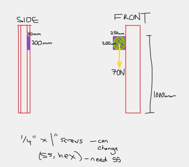
I am trying to design an angle bracket to mount a 70N object to a steel column. It will be made from stainless steel. I am completely new to this - can anyone point me in the direction of what stresses, safety factor etc I need to find to ensure the bracket can hold my load?

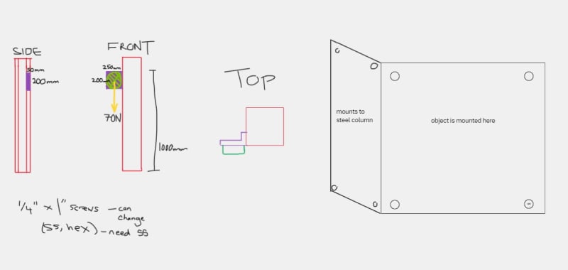
Attached rough image of design:
- purple is the bracket
- green is the object
- red is the column

Short side of the bracket is mounted to the column, the longer side is mounted to the object.
Also new to this website, please let me know if any other info is needed.

ss_annotation_uo12th.jpg
 
Replies continue below

Recommended for you

I don’t see an angle bracket, just a flat plat.
Add a top view image.
Where are the screws to be located?
Have you had a Statics class? A Strength of Materials class?

 
ss_annotation1_ndudnk.jpg


SWComposites:

It's just a typical angle bracket shape, I've added a another image to show.

Yes I have taken a class with statics as a portion, didn't really pay too much attention in it as I was initially going into electrical engineering rather than mechanical. I think I have a general understanding of what I need to know by the end of this problem (bending stress, shear stress, things like that), I just don't know how to start. Is this something I can just analyse like a cantilever beam?
 
Assuming the column is a square hollow tube -
you have two joints to analyze; a) the object to bracket, b) bracket to column
for each joint determine the loads in each fastener: for joint a) should be a simple 70N / 4, assuming the object is centered in the fastener pattern and does not cantilever off the bracket too much;
for joint b) draw a free body diagram of the bracket with each of the fastener loads reacting a vertical shear load and a moment at the bracket corner, where the moment is 70kN * 250 mm/2; now the vertical shear load results in an inplane moment about the fastener pattern center, and the corner moment results in out of plane prying reacted by fastener tension in the upper two fasteners.
for each fastener location check: a) fastener shear, b) bearing in the sheets (accounting for edge distances), fastener tension
and check the bracket corner for shear stress
and depending on the dimensions, check the bracket corner area for buckling
 
SWComposites:
Thanks so much for the guidance!
 
Status
Not open for further replies.

Part and Inventory Search

Sponsor