Continue to Site

Eng-Tips is the largest engineering community on the Internet

Intelligent Work Forums for Engineering Professionals

  • Congratulations KootK on being selected by the Eng-Tips community for having the most helpful posts in the forums last week. Way to Go!

how to solve stress concentration in Abaqus

Status
Not open for further replies.

Sunicetk

Student
Nov 13, 2023
3
12_gansso.jpg
3_zwsghe.jpg
3_wbqpqw.jpg
22_n4vahe.jpg
Hey everyone

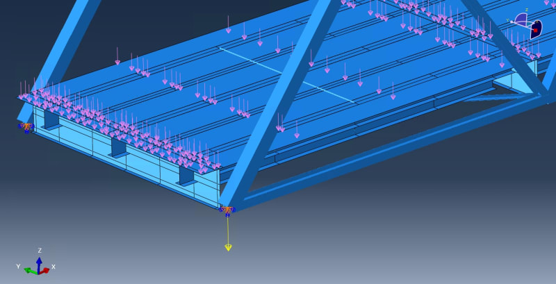
I am doing the simulation of a truss bridge with concrete deck in abaqus.
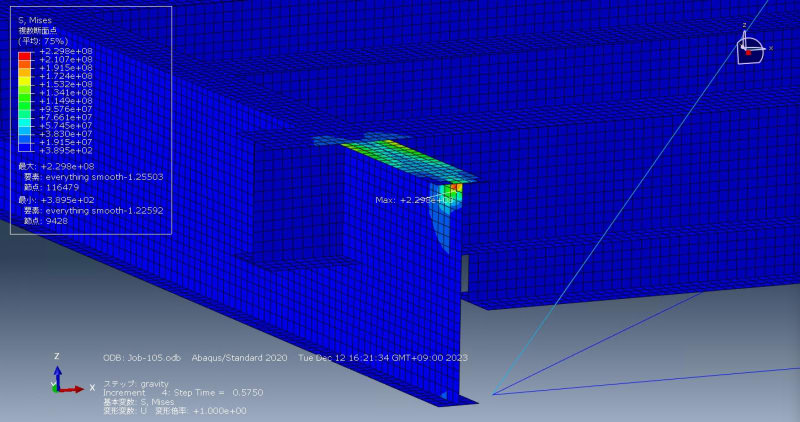
There is a problem that there is typical stress concentration around the top flange of crossbeam and I don't know how to solve it.
The truss is built with beam element and other parts in shell.
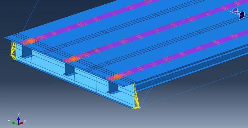
The boundary condition I use is all fixed at the southern 2 nodes and u1 and ur2 allowed at the other 2 support nodes.And I set tie interaction between concrete deck and longitudinal beam, and coupling between edge of crossbeam and truss node.

Now I just apply gravity of the whole structure and pressure as the mass of asphalt. But the stress concentration always exists.
Could anyone of you give me some advice?
 
Replies continue below

Recommended for you

Is there a proper offset in those shells or does the material overlap there (visible with shell thickness visualization enabled) ?
 
the SC exists because there is a) a point load at that point, b) there is some sort of constraint at that point, c) there is some sort of model discontinuity at that point.

the FIRST thing you should plot for any model is the deformed geometry; that will often highlight issues with the model.
 
I wonder why that flange (not the specific stress concentration) is so highly stresses.

As above there are several reasons that maybe this is not real (an artifice of the model). Consider defining your legend so you get more information, maybe a max stress of 1E5 (then all this area will get washed out, but at least you'll see some detail of the strcuture) ?

"Hoffen wir mal, dass alles gut geht !"
General Paulus, Nov 1942, outside Stalingrad after the launch of Operation Uranus.
 
and the lower right picture seems to show some sort of rigid element (yellow) connecting things. Rigid elements are notorious for introducing unrealistic stress concentrations due to their infinite stiffness. Check those connections carefully. And its is typically best to avoid any use of rigid elements unless you are very sure you know what you are doing with them.
 
there are two types of rigid elements (RBE2 and RBE3 in NASTRAN). One, infinite stiffness, will force the set of nodes to maintain their original geometry, deform as a rigid set; the other, zero stiffness, AIUI proportions load to suit the local stiffness (so the set of nodes deform relative to each other).

"Hoffen wir mal, dass alles gut geht !"
General Paulus, Nov 1942, outside Stalingrad after the launch of Operation Uranus.
 
Status
Not open for further replies.

Part and Inventory Search

Sponsor