Eng-Tips is the largest engineering community on the Internet

Intelligent Work Forums for Engineering Professionals

  • Congratulations waross on being selected by the Tek-Tips community for having the most helpful posts in the forums last week. Way to Go!

How do I change the boom lift speed at the end of the operation using hydraulic cylinders and motor? 1

Status
Not open for further replies.

Alex-1985

Mechanical
Feb 5, 2024
9
0
0
UA
Hello there!
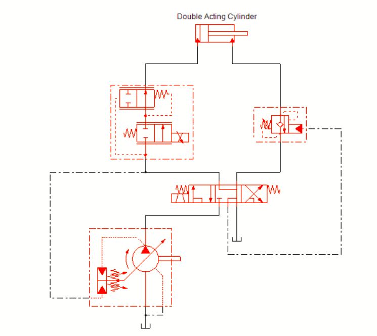
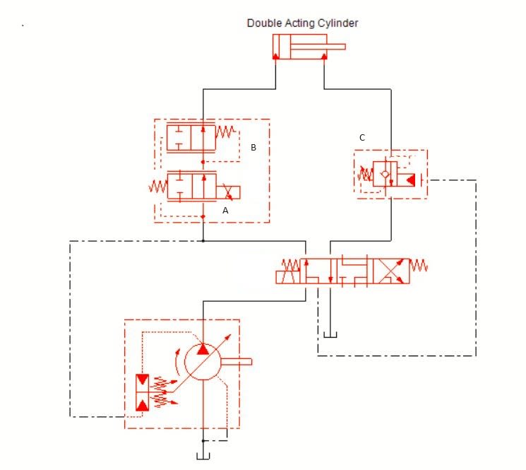
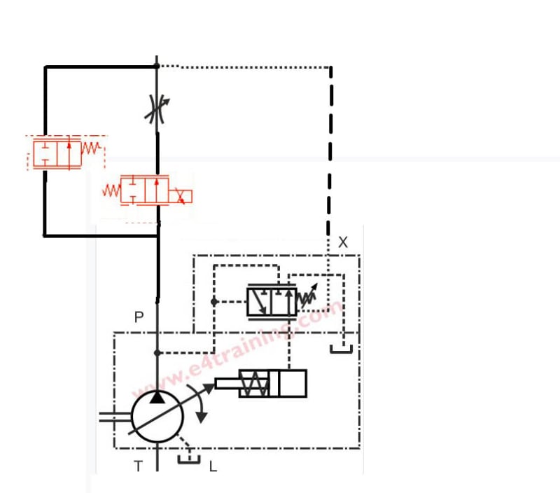
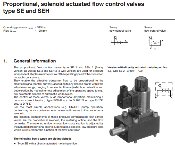
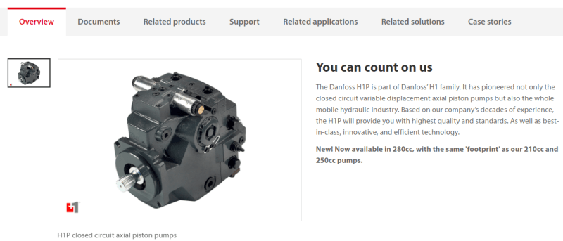
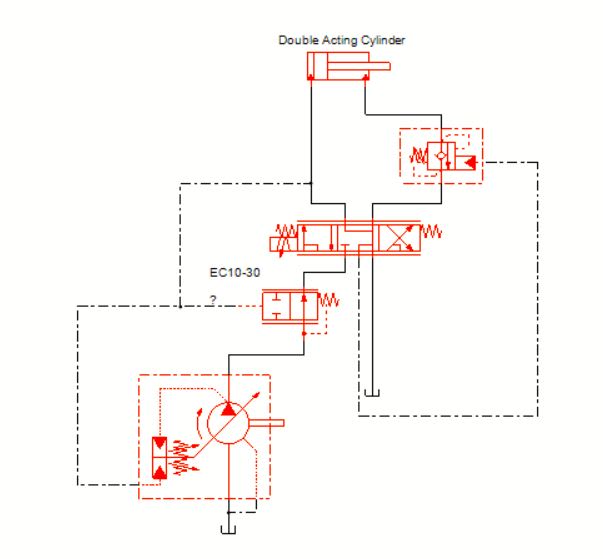
I am designing a boom for load pickup, which also has to rotate. And one of the requirements is to reduce the speed of extension and rotation of the boom at the end of the ligting. What I mean by this. For the first 30 seconds, the boom has to lift at a speed of 0.3 m/s, and for the last 10 seconds, the lift speed has to be 0.03 m/s. I'm not very familiar with hydraulics, I'm just starting to learn it. So far I have realized that I need to use a hydraulic proportional valve and adjustable axial piston pump. I understand a little bit about l-s control when the pump changes pressure if the load on the boom changes. But I can't figure out how to forcibly change the boom extension speed when the boom load is unchanged. Could you please advise me in which direction to look and what equipment to pay attention to? And also how it can be organized.

Thank you!
 
Replies continue below

Recommended for you

A proportional valve is only needed if you need proportional control. If you are okay with "bang-bang" and don't need precision motion control (precision following of a motion profile, precision speed control, precision positioning) then there's lots of ways to do this:

- Dual fixed-displacement pumps. Cut the big-displacement one out of the circuit (short-circuit its output to tank and block its output connection to the pressure side of the circuit) when you need to go slow.
- Or, include a flow-control in the circuit, but use a two-position valve to bypass it when you need to move fast.
 
sys_ygyvpy.jpg


You change the cylinder speed by changing the flow rate into and perhaps out of the cylinder.

A load sensing pump does not change the pressure of a system. The load sensing pump tries to maintain a constant pressure differential and it changes the flow in order to do so.

You need a trigger at some point to cause the flow to change to slow the cylinder when required. When the cylinder reaches position, the flow in or out will change to slow the cylinder. Controlling the flow in or out is dependent on the application. If the external loads can affect the cylinder velocity, it is best to put a motion control valve on the outlet of the cylinder and control the inlet flow with a proportional valve. The proportional valve will need a compensator to maintain consistent performance with changing loads.

If the boom is perhaps working against gravity and you only need to control lowering speed, it best to put the proportional valve on the outlet of the cylinder. You just have to make sure that your system can fill the other side of the cylinder as it moves under the influence of external loads and not under the influence of the system pump.

There are many ways to slow a cylinder and you can spend a little or a lot and still not get what you need. The precision you need will determine the type of valve to use. In simple terms, you just need to control the flow to change the cylinder speed.

There will be people that tell you that it's much more complicated than that, but they are just trying to sell you something. If a cylinder moves, oil or air in going in or coming out. Controlling the fluid flow is the basis of speed control.
 
"So far I have realized that I need to use a hydraulic proportional valve and adjustable axial piston pump. I understand a little bit about l-s control when the pump changes pressure if the load on the boom changes. But I can't figure out how to forcibly change the boom extension speed when the boom load is unchanged."

You control the speed directly with the proportional LS-valve. The speed will be the same regardless if you are lifting no load or max load, that is one of the characteristics of an LS-system. The pump will adapt automatically since it is just trying to keep the delta P over the valve constant.

I don't know if you are lifting 100 tons or 100 lbs but Danfoss PVG32 is a pretty common valve that takes voltage as an input. Parker, Eaton and Rexroth all have good LS pumps.

If you are lowering you will need counterbalance valves to prevent a heavy load from speeding up.

 
First you need to determine not only the two speeds, but also the ramp speeds. So 0.3m/sec to 0.03 m/sec over what time period? And vice versa.

How does the control system know - position sensor / positioner so that the control logic knows when to switch.

Then there are many ways to do it. Two set points on a proportional controller is more precise and able to be modified to suit the reality of what you have once you get it working. but there are more basic ways as well. Like a good operator.

Is this supposed to be automated or operator controlled or what?

Remember - More details = better answers
Also: If you get a response it's polite to respond to it.
 
Thank you for all your replies.
Yes, exactly, I am going to use a cylinder with a position measurement system.
The problem is the next. I vaguely understood how L-S regulation works. The L-S system tries to maintain a constant pressure differential and it changes the flow to do so. But I need a little bit different - 2/3 of the length of the cylinder we lift the weight with the speed 0.3 m/s and the last 1/3 of the length - with the speed 0.03 m/s. So we must adopt (control/set) the flow rate and change it (within 2-3 seconds) at the end of the operation (last 10 seconds). The external control system will get the length of the cylinder and the control system will open/switch to some valve or something. So here is the issue for me - how to regulate the flow rate?
I read the technical documentation about PVG-32 and as far as I understood we can change the flow rate by moving the spool, but as I understand from the documentation, at a constant pressure we can only get 50% of the maximum flow rate.
I found that the flow rate can be changed by changing the number of revolutions of the electric motor of an axial piston pump or by installing a hydraulic throttle. It is also probably possible to change the pump flow rate by changing the angle of the plate in an axial piston pump, but how to do this?
 
Hi Alex

You have moved the discussion to pump control methods. It's fine to do that.

As you know, a load sensing pump will try to maintain the constant pressure drop across the spool. In this case, the spool in the PVG32, for example, will have a pressure drop for a given flow rate. The pump load sense compensator will be set to match the flow for a given spool position, engine speed cylinder speed requirement etc.

If you want to break the link between the pump displacement and pressure drop, there are displacement controlled pumps available when you can change the displacement of the pump with a proportional pressure controller and that will change the pressure in the pump servo piston to move the swash plate and change the pump displacement independent of the pressures in the system.
 
Thank you, FluidPowerUserm, for your answer! Sorry for enjoying, but a little bit confused with your example hydraulics scheme. We move proportional valves "A" and "C" to the left and this will be the full flow, but what position must be to reduce the flow?
work_o2mtkf.jpg
 
That scheme is just one example of how the system might look.

Valve "A" has two parallel lines on the symbol. That means the position of the spool can be infinitely controlled. Therefore, as you adjust the current to the valve, it will open. In your case, you might give the valve 75% of max current to move at 0.3m/s and then back the current off to 30% to get 0.03 m/s. It's a proportional flow controller with built in compensator.

The control system would detect the cylinder position with a switch or linear position sensor (LVDT) and drop the current.

It won't work as drawn, there is no oil flow path in the other direction, it would need a check for reverse flow. It is just a rough example.

You can see that the pump is measuring the pressure differential across the directional control valve. The pump could also be changed to displacement control and the control signal would change the swash angle of the pump to change the flow. It's more efficient that way, but also much more expensive.
 
Ok, it seems I got through your variant and the idea. Yesterday I found some schemes with the flow control. Yesterday I found some schemes with the flow control. There are now two (possibly three) possible solutions in my head:
1. Use a hydraulic throttle (or proportional valves) with a pump that changes the flow depending on the pressure difference behind and in front of the throttle (valves). The approximate hydraulic scheme is below. But here I have a question if I can add L-S regulation here?
var1_xeaudi.jpg


2. The second variant is to use proportional, solenoid-actuated flow control valves. Some engineers gave me this advice, but I need to read more information about it.
Screenshot_Capture_-_2024-02-06_-_14-30-40_pdyydm.png


3. And the third variant is to use displacement-controlled pumps. Something like this
Screenshot_Capture_-_2024-02-06_-_14-39-09_auju71.png


If you have any comments, please, let me know if I am on the right way!
 
Yes, those are the options in a rough sense.

Although, in option 1, the proportional flow control needs to be in the same line as the compensator and you don't need to the variable orifice as they are doing the same thing in controlling flow.

If you go with the load sensing pump option, you can use a proportional directional control valve like this.

sys2_cpne1f.jpg


It has pre compensation and is the same setup as a Danfoss PVG32 valve.

Changing the current to the proportional directional control does the same thing, it changes the flow proportional to the current.

Option 2 is pure flow control

Option 3 is displacement control, another method of flow control really.
 
Thank you!
I started reading technical information on PVG 32. And I discovered that there is a special spool in the distributor that allows you to regulate the flow. As far as I understand, changing the flow rate in a small range at constant pressure is possible, for example, with a spool stroke of only 2-3 mm. If you move the spool further, a pressure drop will occur. I'm not sure I understood this correctly. They then show a graph of the flow rate depending on the spool stroke down to 0. Is this so and is it possible to regulate the flow rate using PVG32?
 
The spools in a PVG32 valve have compound angles on the edges of the spool to modulate the flow very accurately. Other similar spool valves from Bosch Rexroth have the same level modulation. The displacement of the spool is electro-hydraulic, where a direct operating proportional pressure reducer is controlled by a PWM signal from the machine controller. The very precise machine controls that everyone compliments the driver on are actually given by the control of the position of the spool along its stroke, which in the region of 7mm for a PVG32 and the modulating part of the spool being sometimes 50% of the full stroke, depending on the type of machine that the valve is on. If you buy enough valves, Danfoss will cut the spools to your requirements. So will Rexroth and others.

You can have a wide variety of spool cuts, but they always start with a very small flow area and the increment in area with linear displacement tends to be very small. With a load sensing piston pump set to minimum displacement, you might get 6 - 8 LPM from it to keep the pressure up and provide good response to input commands. As the spool moves the first few millimetres, the flow is very small and so are the movement of the actuators. There is not enough pressure drop to cause the pump to upstroke and deliver more flow.

It is only when the operator pulls the joystick a long way and causes large spool movements that the flow area across the spool really opens up and the delta pressure across the spool drops below the setting of the pump's load sense compensator and the pump delivers more flow to increase the pressure drop.

Beyond the modulating parts of the spool, the gain of the valve is large and the ability to do work is a function of the installed power available to drive the pump.

It's not really about pressure drop across the spool, it's more about the pressure differential that the pump sees.

The pump will usually be set to 17-20 BAR (1.7 - 2 kPa). Small movements of the spool with low pressure drop keep the margin (difference between pump outlet pressure and load sense pressure) above 20 BAR. As the flow area opens up, the pressure differential is lowered, below 17 BAR and the pump will upstroke by the required amount to get back to 17 BAR.

A system using a displacement controlled pump will have 2 pressure transducers, one either side of the spool. One measures pump outlet pressure and the other measures the load pressure. The control algorithm will look at the pressures and output a signal to the pump controller to maintain a required pressure drop. Call it electronic load sensing.
 
I started thinking about how to slow down the movement of the boom because that could be a solution too. If you look at the problem from the other side, one of the problems may be the boom slowing down when reaching the desired position. Not only at the end of the cylinder stroke but also in intermediate positions. Can you please tell me the equipment for such purposes that would ensure high accuracy of boom lifting?
 
OK, that's easy to answer, but less easy to implement.

Assuming you want automated position control and not just manual / visual feedback?

Linear position of the cylinder - With a series of switches or an LVDT or some type of device that measures cylinder position. There are companies that will etch a bar code onto the cylinder rod and there are microwave sensors to detect the cylinder position. There are many ways to measure linear position.

You can measure of the angle boom, with an inclinometer, an IMU or something else.

There are loads of the ways to feed the position back to the controller.

The digital controller will be an ECU or something smaller that can execute an algorithm.

The controller will receive the input from the device that is measuring the position or angle. It's doesn't matter what is being measured, the signal back to the controller will be, mostly, a voltage, between 0 - 5V or 0 - 10V. Or, it might be a CAN based message if the system runs on CAN.

The controller will be running an algorithm and the code inside that will have a set of commands that are reading the variables as they come in from the device.


In written form, the code will have a line or series of lines that are looking at the input 'x'. With 'x' being the variable that represents the position of the cylinder. If the variable 'x'>'y', with 'y' being a parameter in the code, then reduce PWM ratio from 100% to 50%.

The cylinder speed slows by 50%.

The code might then say, if 'x'>'z', reduce PWM to 10%. 'z' being the desired final position and at 10% of the rated current to drive the proportional valve, there is not enough current to actually drive the valve. Therefore, the cylinder slows to a stop and doesn't just stop suddenly or overshoot.

If the machine speed is quick and you desire accurate and repeatable performance, then you need PID controller. The PID controller will give you good control. There are tons of videos on PID control out there, have a look on YouTube. See Brian Douglas and others.


I hope this helps a little. I have tried to keep it basic, as it can get complicated very quickly.
 
The rest of us have not seen "the big picture" of what you are trying to do.

Thousands and thousands of hydraulically-operated machines have been built over the years which have absolutely no automation or fancy controls or sophistication and yet still are capable of very fine, although manually-controlled, motions. Tractors. Skid-steers. Forklifts. Cranes. Cherry-pickers (personnel carriers that maintenance people use to get to elevated equipment).

Thousands more machines use "bang-bang" control (valves that are "on" or "off", normal directional valves), and for the jobs that they were built to do, they get the job done ... although the "bang-bang" name is deserved.

For the last couple decades, I've been involved with automation equipment that really does demand fine positioning ... but that's normally nowadays done using servo motors and gear-reducers and (sometimes) ball-screws and other such mechanism, with electric servo control, not hydraulics. No one wants to deal with hydraulic fluid and seals and leaks and noisy pumps and high energy consumption unless they have to.

There are ways to do what was originally described in post #1 by simple means. Of course, if the actual task at hand really is something sophisticated that we haven't been told, and it really does have to be hydraulic and not electric servo + ballscrew, then back to high tech.

So ... Big picture, please.
 
The rest of us have not seen "the big picture" of what you are trying to do.
I agree. A boom is not a rigid structure. The natural frequency will change with load changes and boom extensions. Bang-bang valves may induce oscillations. So will rapid acceleration or deceleration attempts with a proportional valve.
The required motion appears to be very slow. Is there are benefit to moving faster?
I am retired now but I have 40+ years of experience on controlling servo systems of all kinds. Why not provide the big picture because I bet there are a few here that have done something very similar and KNOW the problems the OP will face.


Peter Nachtwey
Delta Motion
IFPS Hall of Fame Member
 
I need a bit of help with the last two questions.

This is a fluid power forum and the question was about driving a boom with hydraulic control and a motor.

There is a big picture, but there are other forums in which to ask the question.

That said, electro-mechanical driving of a boom, of a particular size, would be of the same type. Closed loop feedback control. Sensing position is the same, output would be to a linear actuator.

There is no replacement for the specific power of a hydraulic system. Small and lightweight machine operations are well suited to linear actuators, but if you want high force and robust performance, a fluid power solution is the first option.

I tend to think in terms of motion control and I would be happy to answer this question in a different format, if the question was asked in a different forum. However, I don’t see it as being the right question to ask about the bigger picture in the fluid power forum.

It would be interesting to know more about the application though….
 
I'm trying to prompt investigation of the actual process requirements for speed, accuracy, repeatability, motion profile, etc and the practicality of achieving that with the actual mechanical arrangement, and we haven't seen much of that.

The original post calls for "lifting" 0.3 m/s for 30 seconds (so 9 metres) and then 0.03 m/s for the last 10 seconds (so 0.3 metres). So, is this a "boom" 10 metres long pointing straight up with a 1:1-motion-ratio 10-metre-long hydraulic cylinder? Or is it a 30 metre long boom fixed length starting out near horizontal and lifting up to some (still mostly-horizontal) angle with a much shorter cylinder actuating through a big mechanical disadvantage? What's being lifted, are we talking 10 grams or 10 kg or 10 tonnes? How accurately does it have to be positioned? How accurately does it need to follow that motion profile? By saying 0.3 m/s is it okay if it can do 0.4 or 0.2 as long as the total motion is completed in 30 seconds, or does it really need to be 0.30000 +/- 0.0001 m/s (and if so, WHY, because you are out of your mind)? What's controlling the motion - is it someone watching and controlling a handle by eye (nearly every construction-site boom operates like this - and by "nearly every" I mean every one that I have ever seen without completely excluding the possibility of something that I haven't seen) or is this part of an automation scheme that depends on reliably inserting the moved object into a very carefully-defined spot within tight (specify...) positioning tolerances even though that 10+ (maybe 30?) metre long boom is probably going to be wibbly-wobbling everywhere when the wind blows.

None of this has been presented, and it makes a difference!

Defining actual requirements brings the opportunity to save a lot of money ...
 
Status
Not open for further replies.
Back
Top