Continue to Site

Eng-Tips is the largest engineering community on the Internet

Intelligent Work Forums for Engineering Professionals

  • Congratulations KootK on being selected by the Eng-Tips community for having the most helpful posts in the forums last week. Way to Go!

Defining Datum as Section of Surface

Status
Not open for further replies.

TopPocket

Mechanical
Feb 16, 2022
50
Hi,

First up I'm an ISO guy.

I have a shaft and I want it's axis to define my datum A. The caveat is that I only want a section of the surface be used to define the datum - the first 110mm from on end.

see this image:
engtiups_partial_datum_nnd6ia.png


So I've got two locations defined already, K and L for another feature. I want to say Datum A is only to be taken from between these points.
To me the simple notation by Datum A is a neat way to indicate this, but I'm guessing that it's not the correct way.

Thoughts?
 
Replies continue below

Recommended for you

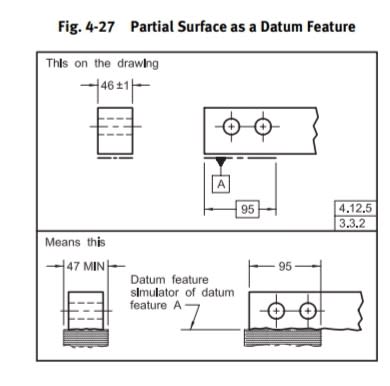
It's from ASME but may be also applicable in ISO.
Luckily you have a cylinder so the datum will be understood as the axis even when the datum feature indicator not attached to the diameter dimension (but to the chain line).
Screenshot_20240220_162134_Drive_qohlys.jpg
 
Thanks for finding this, maybe it applies to ISO. It is fairly clear, but I still think my notation is clearer, even if it's not technically correct. And at the end of the day we're trying to convey information, so I'm tempted to go off book in this case.
 
Under ISO you need to specify a straightness or specify the envelope principle to not accept a noodle.
 
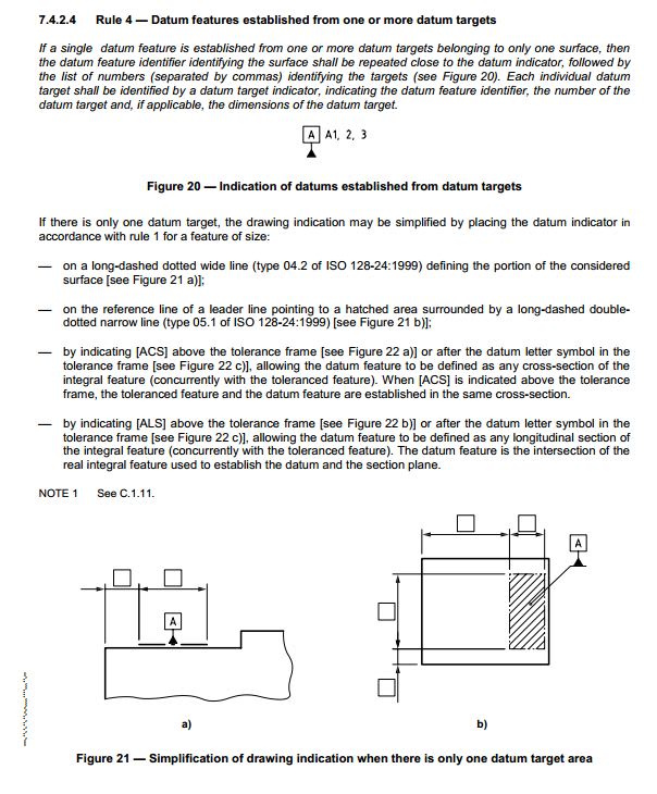
The method Burunduk mentions is not directly applicable in ISO. ISO 5459 requires the datum symbol to be attached to the dimension line of a feature of size under Rule 1 of the standard. To restrict the datum to the first 150mm you could use the dashed line with a datum target. The dashed line should be dimensioned with a TED. I think this is the clearest way to achieve what you're after.

Ryan.
 
Ryan proposed the best method - defining a datum target area.
Equally applicable in ASME and ISO too.
 
Do they have a case where the datum reference frame (or ISO term for it) is defined so that the dimensions have an orientation relative to the part?

For example in "a", are the dimensions parallel to the datum feature (or ISO term for one) or perpendicular to the end surface that is the origin for the dimensions?
 
If datum target locating dimensions are defined relative to non-datum features they are ambiguous. That is true for both stanadards.

Those dimensions are unambiguous only when given between datum features related to the same datum reference frame/"datum system".
 
I knew it was described exactly that way somewhere but I can't find a reference to it. I'm sure the OP would like that reference.
 
pmarc,

Just for my own sake of mind, do you know what are the differences between ASME and ISO GPS relative to the datum targets point of view?

For example:
- A1, A2, A3, is NOT the correct way in ASME (but it is shown, in your ISO embedded picture) adjacent to the datum feature symbol.
- Movable datum targets symbol (bird beak symbol) is always shown horizontal in ASME, but in ISO could be at any angle to depict the direction of movement.

First: Am I correct in my assessments above?
Second: Do you know any other of those subtle “differences” between those two systems?

Thank you so much pmarc


greenimi
A1,2,3 exactly as shown in the ISO figure is now also required in ASME when the datum feature symbol is used in conjunction with datum targets for the same datum feature. See the end of sub-para. 6.3.3.1 in ASME Y14.5-2018 and figure 7-64.
 
3DDave said:
Do they have a case where the datum reference frame (or ISO term for it) is defined so that the dimensions have an orientation relative to the part?

For example in "a", are the dimensions parallel to the datum feature (or ISO term for one) or perpendicular to the end surface that is the origin for the dimensions?

I don't see any example in the standard for datums that would clarify this.

In the other standard (ISO 1101), though, they have the orientation plane indicator which, in theory, could be used to indicate how the target areas, hence basic dimensions, are exactly oriented, but I am not sure it would work in all cases.

Regardless, I personally don't think this should be addressed by adding more datum feature references to the feature control frames, even though starting from 2018 ASME seems to think otherwise (see fig. 12-2 in Y14.5-2018).
 
greenimi said:
pmarc,

Just for my own sake of mind, do you know what are the differences between ASME and ISO GPS relative to the datum targets point of view?

For example:
- A1, A2, A3, is NOT the correct way in ASME (but it is shown, in your ISO embedded picture) adjacent to the datum feature symbol.
- Movable datum targets symbol (bird beak symbol) is always shown horizontal in ASME, but in ISO could be at any angle to depict the direction of movement.

First: Am I correct in my assessments above?
Second: Do you know any other of those subtle “differences” between those two systems?

Thank you so much pmarc

greenimi,

I believe the first bullet has been already answered/adressed by Burunduk. For the second one, yes, you are right. So you know what the answer to your first question is.

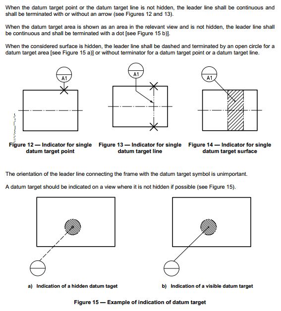
For the second question, yes, there is a bunch of other differences between the two systems. I will just paste a few figures from ISO 5459:2011 to show some examples (hopefully it is enough to see the difference):

Figure 9:
cap1_f9zlty.jpg


Figures 15a & 15b and the associated text:
cap2_igkhit.jpg


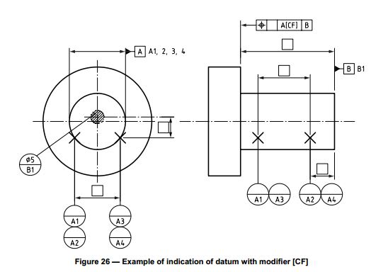
Additionally, in the cases where the type of the associated feature establishing the datum is different than the type of the datum feature itself, datum targets are used and the [CF] indication (Contacting Feature) follows the applicable datum letter in the tolerance frame (as shown in the example below). As you well know, this modifier does not exist in ASME.
cap3_obiuht.jpg
 
Gotta love the redundancy. And the inconsistency. A1, but not A2, A3, A4. Is that because they are concerned about saving the extra millionth of a second it takes for the computer to draw that?

How is the diameter a datum feature when the datum targets don't form a diameter?

 
3DDave said:
Gotta love the redundancy. And the inconsistency. A1, but not A2, A3, A4. Is that because they are concerned about saving the extra millionth of a second it takes for the computer to draw that?
You would have to ask them. I guess you would have to ask ASME as well, since they are now parrotting this practice.

3DDave said:
How is the diameter a datum feature when the datum targets don't form a diameter?
Maybe because by definition datum target is a "portion of a datum feature which can nominally be a point, a line segment or an area". Again, it is much safer to ask them directly to know for sure.
 
Status
Not open for further replies.

Part and Inventory Search

Sponsor