Continue to Site

Eng-Tips is the largest engineering community on the Internet

Intelligent Work Forums for Engineering Professionals

  • Congratulations KootK on being selected by the Eng-Tips community for having the most helpful posts in the forums last week. Way to Go!

Creo 10 - Sketcher

Status
Not open for further replies.

Screwball_1

Mechanical
Mar 3, 2024
9
Hello,

I've been away from Creo for about 5 years, but have now got back into it. I'm really having a hard time with sketcher. When I used it before, they had what was called Intent Manager. You could turn it off. I can't find that anymore. What happened - or maybe better - what did I miss. Is there somewhere to find some tutorials on sketcher, or other parts of Creo for that matter.

Disclosure; I am using a student version as that is all I have available. The PTC student help doesn't seem to be very good, or maybe I don't know how to find it either.

Thanks in advance,
SB
 
Replies continue below

Recommended for you

The user guide is on line and the main difference between the student and commercial versions is the inability to save and play trail files and interoperability between the two version's output files. As far as I know the way the software works is the same.

I also recall that Intent Mangler became a full-time function.
Are there some specific problems?

See
 
Yeah the sketcher evolved quite a bit since it was called Intent Manager. Intent manager functionality can't be turned off.

Best way I can explain it, Sketcher fully constrains every sketch, all of the time. Light grey dimensions show up to reach fully constrained status. Ignore them and build your dimensions and constraints as you want them. When all of the greys are gone your sketch should be fully constrained. You can click on any auto dimension that you want to keep and promote it to a 'strong' dimension, although that takes about as many mouse clicks as making a fresh dimension. Plus if I make a fresh dimension I can make it from entity-to-entity instead of endpoint-to-endpoint (stronger).

You'll want to study all of the constraint symbols and make sure they're visible. Also the old school philosophy of keeping sketches relatively simple still pays off.

The one thing you don't want to do, is leave grey dimensions. Your sketch will be unstable. I think they do it this way to copy the SolidWorks behavior. This IMNSHO is one of the major disasters in parametric CAD in the last 15 years. (Along with non-sequential assembly constraint evaluations - what I call 'constraint soup' - which is a whole other mess)
 
Thanks for the replies, those are helpful.

IMNSHO they turned sketcher into a disaster by not allowing Intent Manager to be turned off. I used to make complex sketches (lettering) without it and liked the fact I could control them as I went along. I could add dimensions and constraints as needed to control the sketch while having the ability to move geometry as needed - and 9 million weak dimensions were not in the way. Not any more. Shame on you PTC.

That said, a couple of quick questions;
1) I see dimensions with one normal arrow and one that is red. What does that mean?
2) Sometimes when I pick on a dimension to make it strong or change it, it opens the box but the numbers turn red and I can't do anything to it. So I have to start over. It creates so many useless picks. What is going on here?

Again, thanks for the replies

 
That might be newer stuff. I got up to Creo 8.

Maybe there is a way to hide the weak dimensions, but there's no way to make them go away.

The actual lettering functionality in sketcher has improved, maybe that could simplify your work.
 
I don't do lettering anymore and their internal letters wouldn't help (car tire lettering so it was our design). Thank goodness for that, I would be out of hair and cuss words. I guess I'm too old school but I hate Intent Manager and now sketcher with every inch of my body. I struggle with simple sketches and spend way too much time fighting that instead of creating models and assemblies.

I have played with the settings which has helped, but still a struggle. Other than sketcher I like some other things PTC has done since I left it years ago.

Thanks again for the replies. I will have more questions as I find the Student version of help not on the same level of commercial it seems. I have a .edu e-mail which allows me to get Creo, which I prefer, over Inventor or Solidworks.
 
I found a really nice way to handle complex things is to use some other method to create the geometry and then import it to where it needed to be. Then in Sketcher "Use Edge" to copy that geometry into the sketch. The automatic constraints nail the sketched geometry in place and there are no dimensions.

Keep at it for the simple stuff - I find that too often those who really hate it are trying to bite too big a chunk of geometry to start with and then going back to add the constraints they want.

Like, putting in 20 instrument panel openings and all the screw holes and then coming back to dimension them. It easily becomes a mess.

One simplification that really helps is to start off with centerlines and points; nail down the locations and the dimensions to the centerlines and then relate sketched lines and circles. The result for circles is the circle is controlled by one dimension - diameter or radius, not by three. It's also better when someone wants a slot instead of a circular hole as the location dimensions, to the centerlines, don't go away, so the drawing isn't f'd up so much.
 
I agree completely. I had to use complex sketches to do what we had to do, but even then, breaking them up into pieces (sketches) made a huge difference. You can then later use the "use edge' which I think now looks like a "project" command to get the geometry you want to extrude, cut, whatever. Multiple sketches (datum curves) could be turned into one feature.

At the end of the day it's about what we are trying to design, how we control our models, and how what we called in the old days "design intent" or "parent/child" relationships. This holds true in part and assembly. I've found PTC has gotten better with the modify part in assembly mode but one must still be aware of the relationships you are creating.

Which is another question. Is there a config.pro setting to control assembly created relationships when modifying a part? IOW, if I am working on an assembly and make a part active, can I prevent this part from using another feature of another part as a reference? Hope that makes sense.

Thanks again for the replies.
 
Here's the latest:


I normally used it to figure out things for users that had created circular references


I don't recall an option to shut it off; it did not seem too difficult to not select things that I did not want to use for references. One could certainly hide the parts or create a simplified rep if the simp rep function was part of the license. Or just open the part directly, outside the assembly.
 
Yes.

This is where I get confused. We have an assembly with a bunch of parts, but we don't know how they will go together by the time the design is done. As usual. It is good to be in assembly mode to see everything, and how the parts might fit together. Probably a bunch of changes as well.

Let's say we have some bolt holes that we want to follow from part to part. If one part changes the location, the other part changes as well. So in assembly mode we make a part active and use the hole in the other part as a reference. A good thing, and planned, saves us time down the road.

Then, in the same part, we want to create another feature, and it is totally independent from the other parts. Yet, once in sketch mode, the software wants to use the other parts as references in the sketch - we don't want that. If you open the part itself, you don't have the advantage of seeing the assembly (or simplified rep).

Is this (possible) relationship in assembly mode a product of a sketcher setting or a general Creo setting?
 
Adding; it seems to me this should be a toggle. A config.pro option, or maybe even a button. I have no idea.
 
That is a bad plan. If you want coordination create a skeleton part that has only points and axes and the like and use that as references for the individual parts. Don't create references for part features directly part to part in assembly mode if you aren't planning on being a great juggler. Most people aren't.

Better yet, use layouts - this allows the values for dimensions to be shared among parts while still allowing the individual parts to retain their own displayable dimensions and, if required, associated tolerances.

"Then, in the same part, we want to create another feature, and it is totally independent from the other parts. Yet, once in sketch mode, the software wants to use the other parts as references in the sketch - we don't want that. If you open the part itself, you don't have the advantage of seeing the assembly (or simplified rep)."

If you are in assembly mode it should not try to use anything you don't tell it as a reference. I cannot imagine the sketcher looking at 40,000 edges, 200,000 vertices, and 5,000 faces and including all of them on the off chance your sketched entity is near one of them. The simple answer is open the part, rough in the sketch and feature and then go back to the assembly and make dimension adjustments so no references are made.

Layout eliminates that completely. If you don't want to redraw a new sketch in one part to match an existing one, save the sketch and reuse it in the other part; this is another advantage of using centerlines and the like - if you align centerlines to part features you can simply align them in the other part and all the dimensions from them will be retained, saving all that work. Then link the values to the layout and they are coordinated from there on.
 
Thank you and good stuff. I never thought of layout. I'm having enough trouble with sketcher. :) I'm dealing with a 20 part assembly that I had know idea how it might turn out. I use relations and parameters for some things, so everything updates as they should.

To the second part; it should not be looking at all those other things, but it seems to. I messed around with my basic setup (default constraints) which helped. At times I wonder if this isn't a student version (all I have) thing. For example, if I try to modify the hatch on a cross-section (assembly mode), it blows up. Gone - see you. Thanks.

I know that's an entirely different problem, but I don't imagine PTC spending a bunch of money updating the student code.
 
They don't have separate code for students. It's the same code as for production, just with some features turned off. They won't be issuing bug fixes, but they also don't want to ship known bad code as the goal is to get students to like them and get their employers to buy what the student liked.

Stuff blowing up? Do you have a Quadro card or a gamer card? PTC usually works with gamer cards, but the gold standard used to be the Quadro because the drivers from PTC expected to see the features act the way they do in Quadro cards. Gamer cards are built with slightly different priorities.

That goal is why they got rid of the home engineer license - basically a student software - no trackable sales. PTC is ruthless when it comes to money. I think they aren't as focused on long-term expansion, but it's not my company.

Layout is mind numbingly stupid - Nothing there is parametric; it is a place to collect relationships and numbers related to dimensions. It should have been named Napkin. Nothing is even to scale unless you work really hard.

But, suppose you have a beam that is 200 feet long and a 12 inch X 12 inch square hole pattern at each end.

You draw a rectangle to represent the beam, and some lines for the hole centers and maybe one or more of the holes. All on a letter size page. Just like a napkin. Put in the dimension from the end of the beam. Dimension the length of the beam. Dimension the hole patterns. Dimension a hole. In the full scale part on the screen the holes will be little dots you can't make out. You put in the values and when you get to the model you say - this dimension value on the model is driven by that dimension value on the layout. Every thing that uses that layout can use the dimensions the CAD user has said are important.

One can rough out the entire amount of relationships between features in the layout, just like one used to do with a pen on a napkin.
 
Not a gaming computer. It is a souped up laptop built especially for CAD work. Plenty of memory, top of the line video card. It's basically a clone of the one I used when I was still in the industry, and not cheap.

I only do this as fun making models to be 3D printed. I'm not familiar anymore with layout and I don't want to spend the time to re-learn it. If I remember right, years ago when I looked into it I wasn't that impressed. It may have changed since then.

I think there are simpler solutions to my problem, I just have to find them.

Thanks again for the help and advise.

Before anyone tells me Creo is overkill for 3D printing, I understand and agree, but it's the software I am most familiar with, even though I have been away from it for a few years. Many use Autodesk Fusion 360 (played with it), Tinker CAD, and the other tinker toy CAD systems they use. I don't want to learn a new CAD system. I also have Solidworks and Inventor. Solidworks is OK, and Inventor...I'll just stop there.
 
Just a follow up on why I was asking all the questions above. Thanks again for all the help.

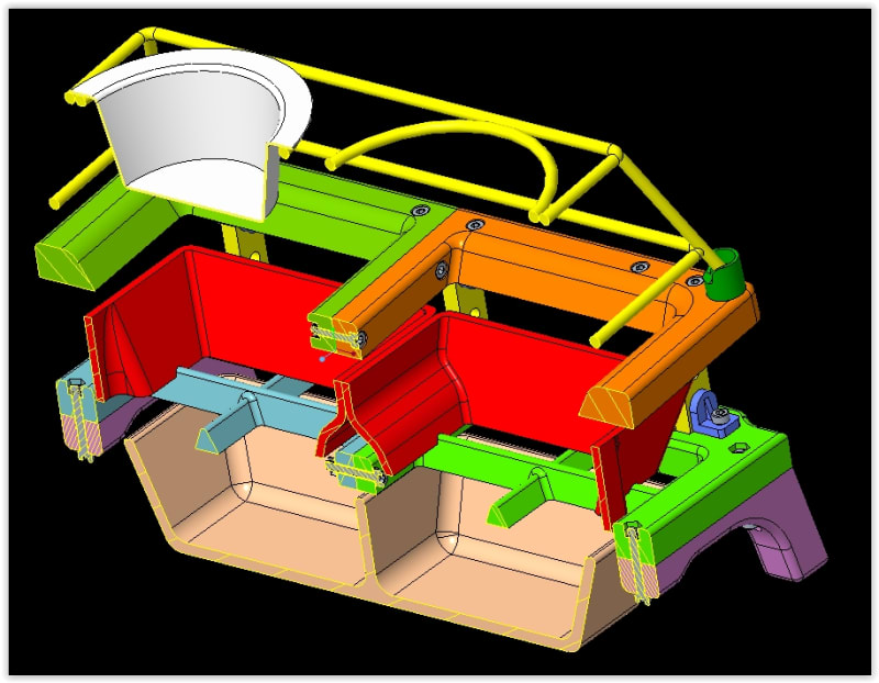
As I said above I'm playing around with 3D printing. Want to design a stand to get my pet bowl off the floor. Over the top, but it was fun to design. You have no idea what you are going to end up when you start. The yellow part and bowl is what I had to work around.

STAND_2_vfmlfu.jpg
 
Status
Not open for further replies.

Part and Inventory Search

Sponsor