I am currently working on a FE simulation project where a tensile test of DP800 steel is subjected to cyclic loading. The reference we are using is:
It utilizes Yoshida Uemori model (YUM) to formulate the modulus of elasticity (E) to simulate the hysteresis caused by cyclic loading.
We are using a USDFLD subroutine in ABAQUS CAE to formulate the E according to the cyclic loading i.e. using a FORTRAN code, we save the ratio of 'current E' (using YUM) to 'initial E' as a state variable to simulate the process using this ratio. The code recognizes the loading and unloading stages in the curve correctly after checking the PRINT statements in it (Please refer to the code snippet below)
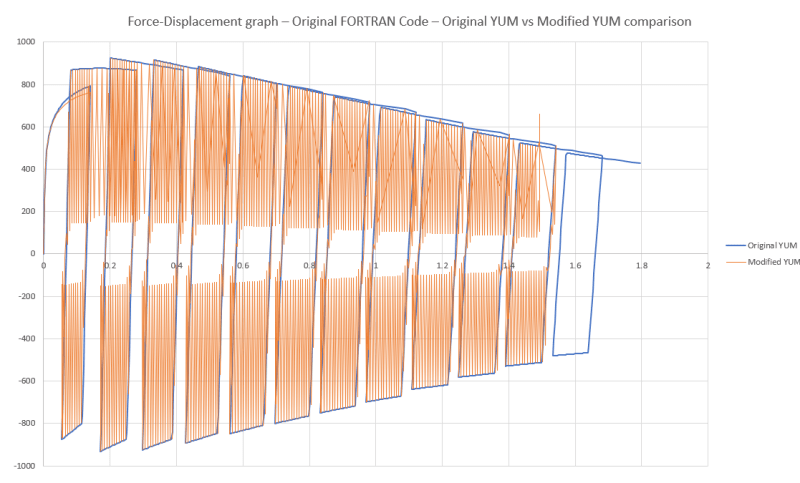
To check the FORTRAN code, we used a RVE (a simple cube element). Original YUM formula mentioned in the research paper works correctly. The modified YUM formula gives negative E values at certain time points which can be seen as the oscillations on the Force-Displacement curve of Modified YUM formula. (Please refer Image1 below)

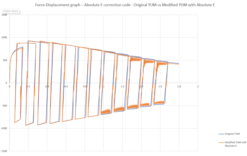
I modified the FORTRAN code to convert the negative E values to absolute values so it is always positive. This gave us almost the correct trend in the Force-Displacement curve. (Please refer Image2 below)

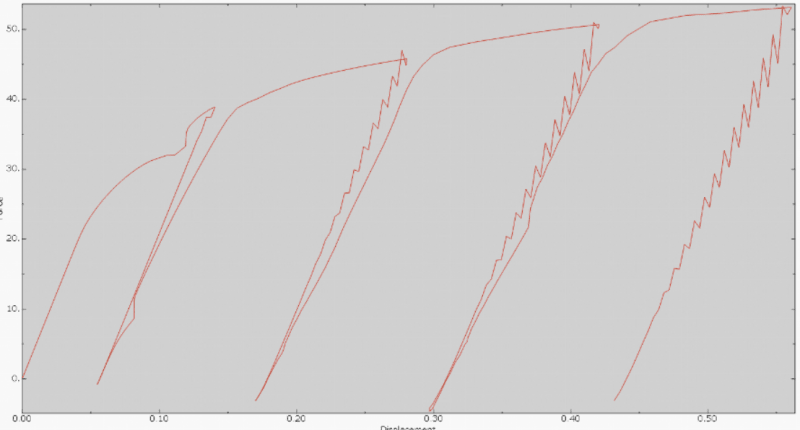
I wanted to test this code on the tensile test sample which is a notched tensile test specimen but it does not display the hysteresis as expected. Also, the simulation crashes so the image does not show the complete process (Please refer Image3 below)

I would appreciate any tips or suggestions as to how to simulate the hysteresis caused by cyclic loading on a tensile test specimen.
Thank you.
It utilizes Yoshida Uemori model (YUM) to formulate the modulus of elasticity (E) to simulate the hysteresis caused by cyclic loading.
We are using a USDFLD subroutine in ABAQUS CAE to formulate the E according to the cyclic loading i.e. using a FORTRAN code, we save the ratio of 'current E' (using YUM) to 'initial E' as a state variable to simulate the process using this ratio. The code recognizes the loading and unloading stages in the curve correctly after checking the PRINT statements in it (Please refer to the code snippet below)
Code:
		CALL GETVRM('SINV',ARRAY,JARRAY,FLGRAY,JRCD,JMAC,JMATYP,MATLAYO,
     1     LACCFLA)
			   SvM = ARRAY(1)

		current_von_mises_stress = SvM

		IF (KINC .EQ. 1) THEN
		   ! For the first time step, current and previous Von Mises stresses are equal
		   previous_von_mises_stress = current_von_mises_stress
		   peak_stress = 0
		   stress_ratio = 1
		ELSE IF (KINC .EQ. 2) THEN
		   previous_von_mises_stress = STATEV(11)
		   peak_stress = current_von_mises_stress
		   stress_ratio = 1
		ELSE
		   ! For subsequent steps, retrieve the previous value using STATEV
		   previous_von_mises_stress = STATEV(11)
		   peak_stress = STATEV(12)
		ENDIF

		IF (current_von_mises_stress .GT. previous_von_mises_stress) THEN
		   IF ((peak_stress .LT. current_von_mises_stress) .AND. (peak_stress .LT. previous_von_mises_stress)) THEN
		   ELSE
			  IF (KINC .EQ. 2) THEN
			    peak_stress = current_von_mises_stress
			  ELSE
			    peak_stress = previous_von_mises_stress
			  ENDIF
		   ENDIF

		   PRINT *, 'Loading stage'
		   ! Print the peak equivalent stress of the current loading stage
		   PRINT *, 'Peak equivalent stress for current loading stage:', peak_stress

		   ! Print the current increment number where loading begins
		   PRINT *, 'Loading increment number:', KINC

		   IF (KINC .EQ. 1) THEN
		      stress_ratio = 1
		   ELSEIF (KINC .EQ. 2) THEN
		      stress_ratio = 1
		   ELSE
			  stress_ratio = current_von_mises_stress/peak_stress
		   ENDIF

		   PRINT *, 'Stress Ratio: ', stress_ratio

		   ! Modified YUM formula for loading
		   E = E_init*(1-STATEV(1)*c1) - (stress_ratio)*(E_init-E_saturation)*(1-exp(-psi*PEEQ))
		   PRINT *, 'Modulus of elasticity: ', E

		   PRINT *, '' ! This line prints a blank line
		ELSE IF (current_von_mises_stress .LT. previous_von_mises_stress) THEN
		   IF ((peak_stress .GT. current_von_mises_stress) .AND. (peak_stress .GT. previous_von_mises_stress)) THEN
		   ELSE
		      peak_stress = previous_von_mises_stress
		   ENDIF

		   PRINT *, 'Unloading stage'
		   ! Print the peak equivalent stress of the current unloading stage
		   PRINT *, 'Peak equivalent stress for current unloading stage:', peak_stress

		   ! Print the current increment number where unloading begins
		   PRINT *, 'Unloading increment number:', KINC

		   stress_ratio = current_von_mises_stress/peak_stress
		   PRINT *, 'Stress Ratio: ', stress_ratio

		   ! Modified YUM formula for loading
		   E = E_init*(1-STATEV(1)*c1) - (1-stress_ratio)*(E_init-E_saturation)*(1-exp(-psi*PEEQ))
		   PRINT *, 'Modulus of elasticity: ', E

		   PRINT *, '' ! This line prints a blank line
		ELSE
		   E = E_init
		   PRINT *, 'Modulus of elasticity: ', E
		ENDIF

		! Original YUM formula
		!E = E_init*(1-STATEV(1)*c1) - (E_init-E_saturation)*(1-exp(-psi*PEEQ))

		PRINT *, 'Peak stress: ', peak_stress
		PRINT *, 'Previous equivalent stress: ', previous_von_mises_stress
		PRINT *, 'Current equivalent stress: ', current_von_mises_stress
		PRINT *, 'Percentage: ', E/E_init
		PRINT *, '' ! This line prints a blank line

	   STATEV(9) = E/E_init
	   STATEV(10) = E
	   STATEV(11) = current_von_mises_stress
	   STATEV(12) = peak_stress
	   FIELD(1) = STATEV(9)
To check the FORTRAN code, we used a RVE (a simple cube element). Original YUM formula mentioned in the research paper works correctly. The modified YUM formula gives negative E values at certain time points which can be seen as the oscillations on the Force-Displacement curve of Modified YUM formula. (Please refer Image1 below)

I modified the FORTRAN code to convert the negative E values to absolute values so it is always positive. This gave us almost the correct trend in the Force-Displacement curve. (Please refer Image2 below)

I wanted to test this code on the tensile test sample which is a notched tensile test specimen but it does not display the hysteresis as expected. Also, the simulation crashes so the image does not show the complete process (Please refer Image3 below)

I would appreciate any tips or suggestions as to how to simulate the hysteresis caused by cyclic loading on a tensile test specimen.
Thank you.
