Continue to Site

Eng-Tips is the largest engineering community on the Internet

Intelligent Work Forums for Engineering Professionals

  • Congratulations IDS on being selected by the Eng-Tips community for having the most helpful posts in the forums last week. Way to Go!

Secant Pile Structure to Resist Lateral Load 1

Status
Not open for further replies.

mole20

Civil/Environmental
Feb 8, 2022
4
Hello everyone,

I am designing a structure using secant piles to provide the thrust resistance needed to push a tunnel-boring machine in the ground. The contractor's concept involves three rows of secant piles, with approximately 10 feet sticking above the ground. I am considering using LPILE or RSPILE to model the structure as a pile group.

Has anyone here designed a structure like this before, and if so, what analysis tool did you use?

Thank you for your suggestions!
 
Replies continue below

Recommended for you

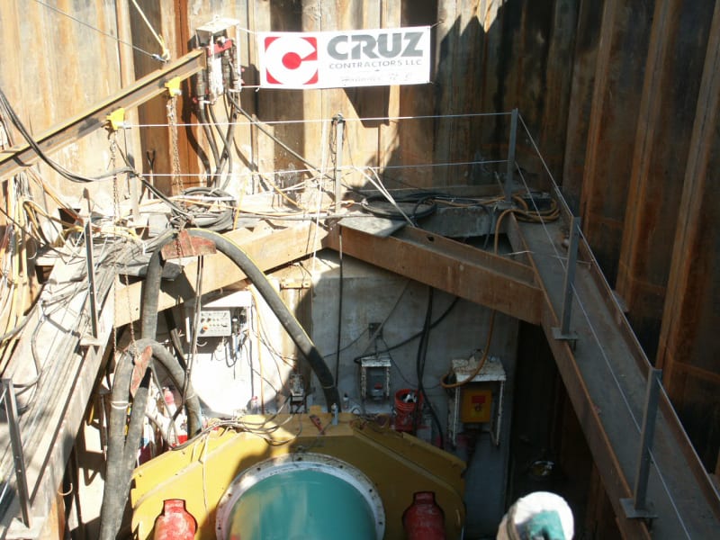
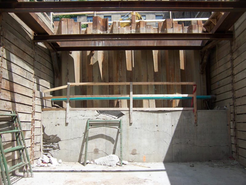
I have designed reaction backwalls for pipe and tunnel jacking forces up to 2,500,000 pounds. I usually design a reinforced concrete block to spread the load along a steel sheet pile backwall. The block is usually about the same width as the jacking pit and about 10 feet high. I design the sheet pile wall for passive resistance. With a safety factor on the jacking force, I calculate the required depth of backwall below the pit depth. I then calculate the bending moment and shear on the sheet pule backwall. I also recheck the backwall for a trapezoidal reaction pressure distribution on the backwall and then check the bending and shear. I design the backwall for the worse case bending and shear. These designs have worked fine. Whenever I needed a sheet pile size greater than what is available, I doubled up and used a double SSP backwall with the walls very closely driven (as close together as possible).
PICT2202_blsky2.jpg

Jacking force was 714,000 pounds.

100_2562_egimuq.jpg

Jacking force was 2,500,000 pounds.
The cracks in the concrete block in the 2nd photo are from starting the demolition of the concrete block after the concrete pedestrian tunnel was jacked under the road.


PEinc, thank you for your response! Most of the thrust blocks I've designed in the past resemble those shown in the picture. However, the thrust block I'm currently designing is a bit different. Due to the critical structures behind the shaft that need to be protected, we can't pour the thrust block up against the Shaft Support of Excavation (SOE) to spread the load. The solution here is to create a "free-standing thrust wall" made up of secant piles, positioned away from the Shaft SOE.
 
Thrust block or not, the jacking load is still pushing on the soil (passive wedge). How far away is the "critical structure" from the secant pile wall? For my first photo, the project engineer worried about their critical building behind the backwall. I showed them that the passive wedge of soil did not come anywhere close to the building. They backed off. No problems encountered.

 
The critical structure is literally up against the Shaft SOE.
 
Status
Not open for further replies.

Part and Inventory Search

Sponsor