Eng-Tips is the largest engineering community on the Internet

Intelligent Work Forums for Engineering Professionals

Do these deck beams look stable to you? 1

Status
Not open for further replies.

Mike Mike

Structural
Apr 27, 2019
136
0
0
TH
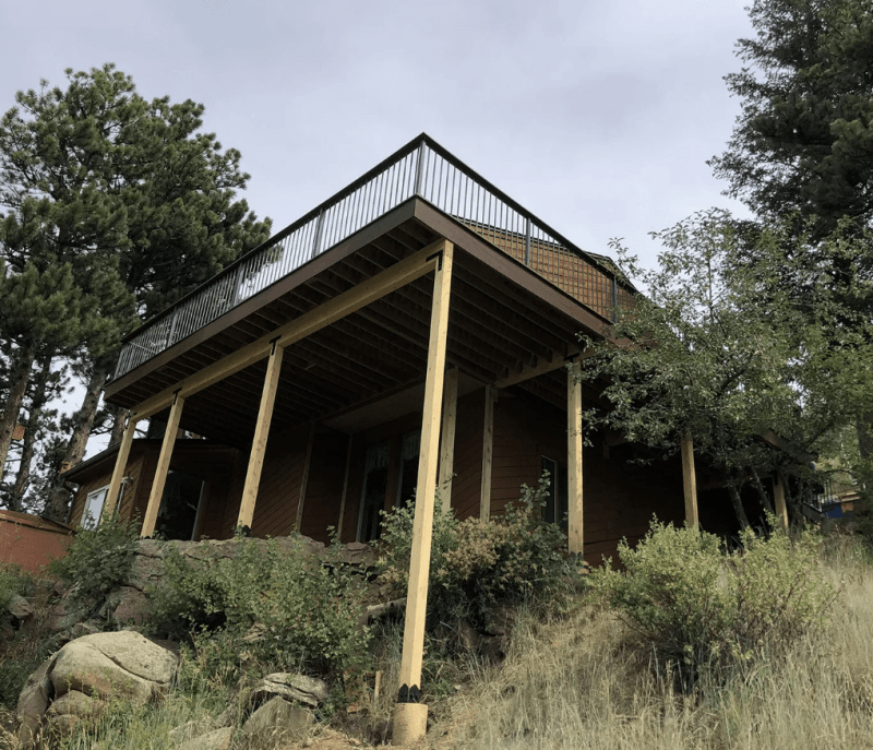
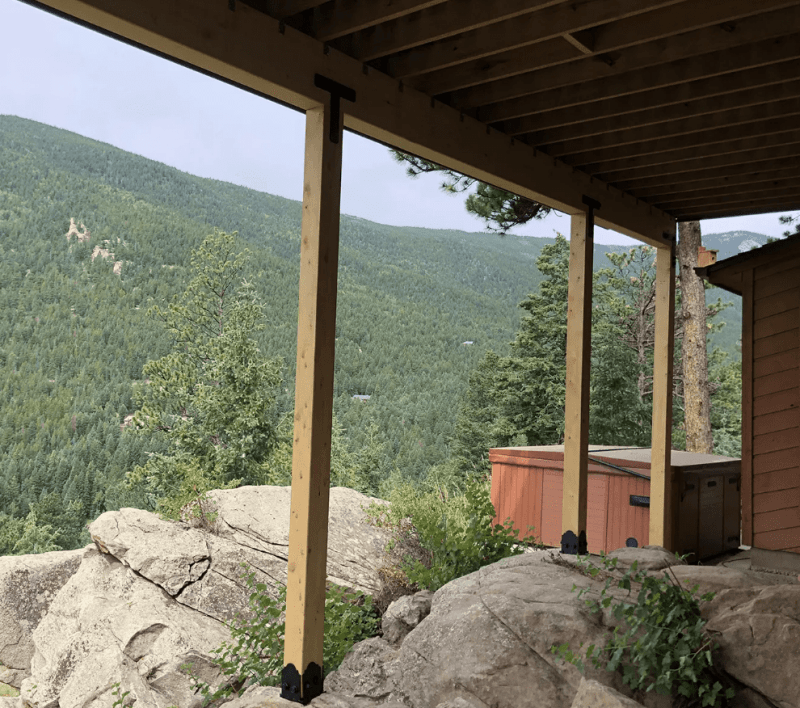
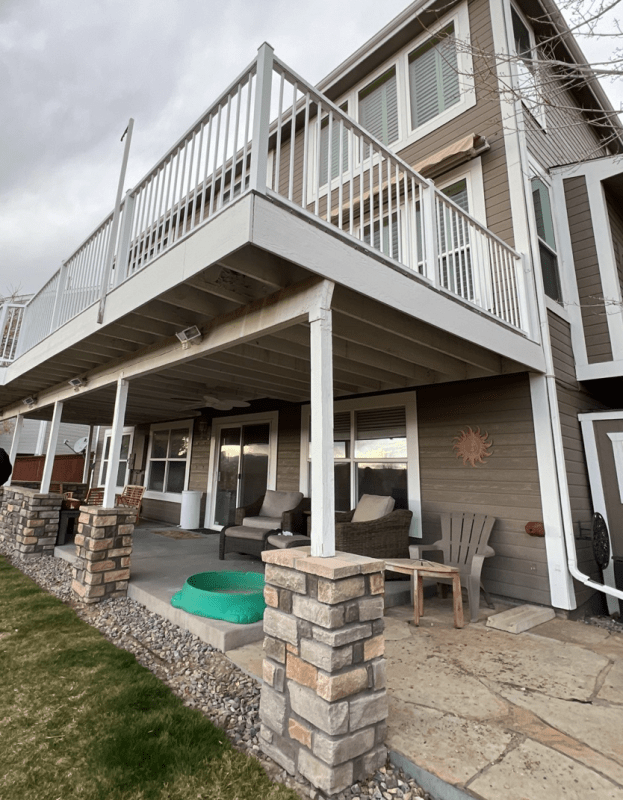
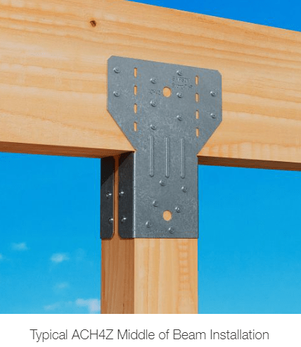
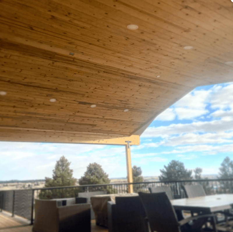
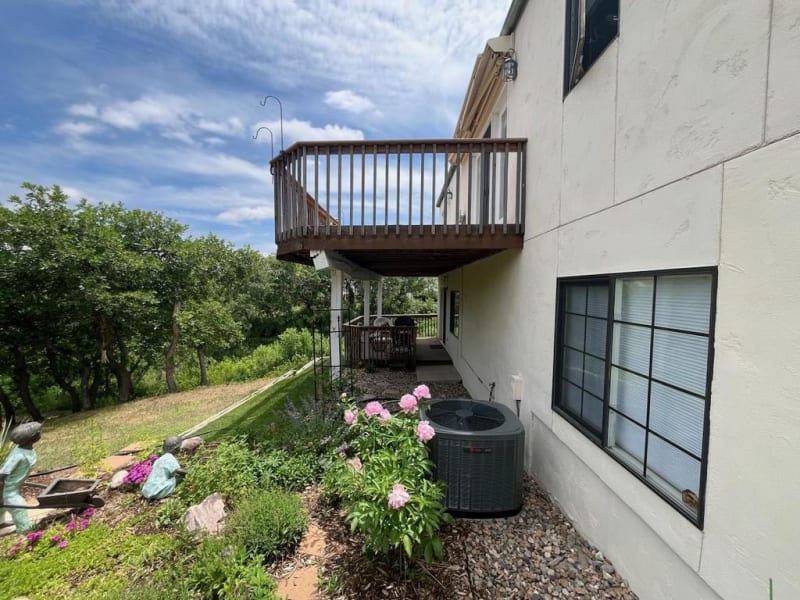
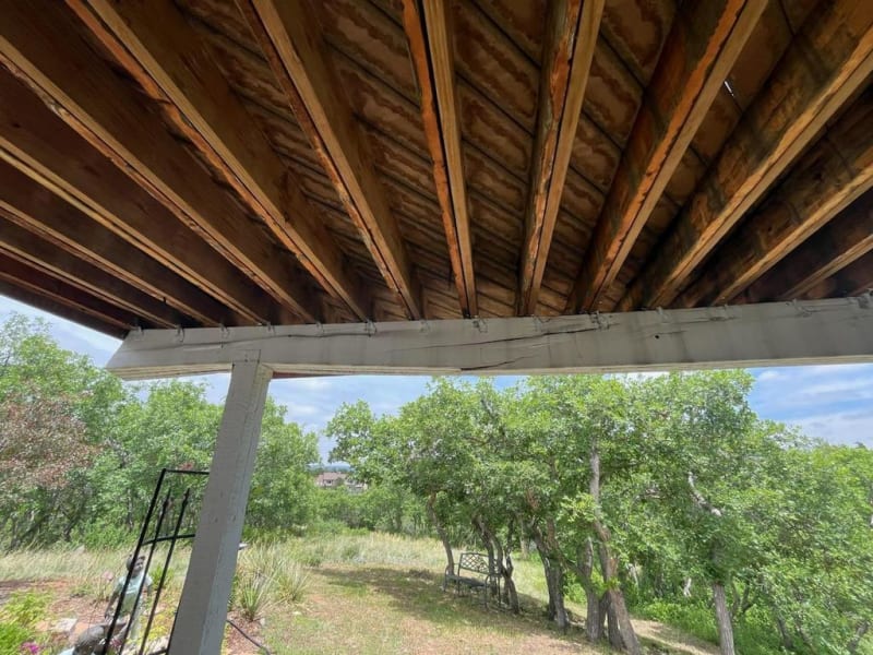
Do the dropped beams in the photos below follow the intent of the code? This seems to be industry standard deck construction, and there is pressure from contractors to go along, but I'm not a fan for 2 reasons:
1. The bottom of the beam is in compression where continuous over posts and wants to kick out to the side. 2024 NDS 3.3.3.4 says "lateral support shall be provided at points of bearing to prevent rotation." I guess a hefty post cap could prevent "rotation", but not "lateral" translation. I read thru the NDS commentary and AWC NF&PA TR14 Lateral Torsional Stability but did not find any additional guidance. I don't feel great about it, but owners are not okay with stabilizing kickers or blocking on most jobs.
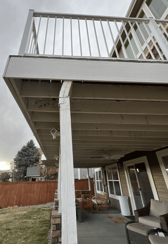
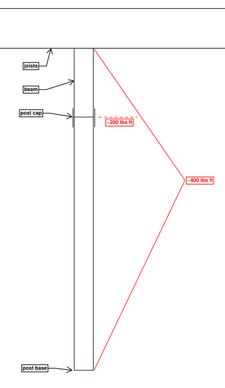
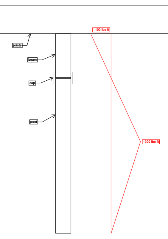
2. Anyone who happens to push on the post puts the beam in perpendicular to grain bending, and counts on moment transferring thru a post cap couple, which will rotate significantly before the cap engages. A typical moment diagram is sketched in red below. The moment is small, but I don't feel great about it.

Screenshot_2024-05-25_212811_bp6xhg.png

Screenshot_2024-05-25_213107_g3nvw0.png

Screenshot_2024-05-25_213630_eebfpb.png

Screenshot_2024-05-25_213651_lk4i4a.png

Screenshot_2024-05-27_123212_dhkvrd.png
 
Replies continue below

Recommended for you

Section R507.5.2 of the 2018 IRC states that the post to beam connection must resist horizontal displacement. In at least one photo the horizontal displacement does not appear to be resisted. Not very stable looking to me.

Simpson's decorative "T" and "L" hardware are rated for uplift and lateral (in plane) load resistance but not bending. I don't know if the hardware in the photos are Simpson brand or not but I would not think that the rated load resistance would be much different.
 
You are correct - not stable and not code compliant...though most inspectors will see some sort of Simpson connection and say okay. I'm pretty sure the prescriptive (here we go again...) section of the floor chapter for decks just says you need a post cap and it's okay. Unfortunately, the post caps have in their literature that they aren't suitable for the purpose of restraining rotation. I'd be willing to call it good with some heavier steel plates and a bit of analysis...but the thin stuff from Simpson is no good there.

The worst part about the top picture, though, is probably the 6x6 that's a good 20' long. Probably just squeezes in under slenderness rules, but yikes. The other worst part about it - it looks like a free standing deck. The house floor framing is cantilevered over the back door and there looks to be an offset between the ledger and the wall, so it's a single ply beam. The post arrangement seems to suggest the same. So it has minimal positive connection back to the house, no lateral restraint on the outer edge...this whole deck looks really sketchy to me.
 
Are you also questioning the restraint of the joists at bearing on the header? It looks like the main stabilizer there is the rim board. I keep thinking blocking at the bearing on the double header is what you really want "per NDS".
 
Looks like there are a couple questions in the OP.

Mike Mike said:
The bottom of the beam is in compression where continuous over posts and wants to kick out to the side. 2024 NDS 3.3.3.4 says "lateral support shall be provided at points of bearing to prevent rotation." I guess a hefty post cap could prevent "rotation", but not "lateral" translation.

This is a prescriptive design requirement, as a shortcut to prevent or requiring a design profession to perform a LTB check. However, LTB is fairly straightforward to perform, and with it, you can see for yourself whether the beam with inverted moment is acceptable as-is, or if it requires lateral restraint at column locations. Combine Table 3.3.3 of the NDS with equations 3.3-5 and 3.3-6 to determine the reduced allowable moment, or if you prefer another approach, plug in your actual design critical moment and back calc the required bracing interval to meet the requirements of your beam.

Mike Mike said:
Anyone who happens to push on the post puts the beam in perpendicular to grain bending, and counts on moment transferring thru a post cap couple, which will rotate significantly before the cap engages.

Your post is treated as a pinned/pinned connection, and it's up to you to determine the methods to achieve this connection type. As shown in the photos, not a good way to transfer lateral shear as you've described, a column cap would probably help with that, however. With wood design, I would assume the moment is only in the column, and there is no moment transfer at the beam (pinned/pinned), and thus, would not be concerned with a rotational moment at the beam base for this design scenario.

I 100% agree with Pham, first thing I saw that concerned me on this was the slenderness of that rightmost column, maybe it works out, but it does give some concern.
 
Thanks all, great to hear I'm not crazy. I agree there are potentially global lateral load path issues, post slenderness issues, and joist stability issues. But I'm focusing on the beams because this issue is the most common. It occurs on more than half my decks. Also this is the one issue I can't correct. If I require lateral restraint at beam bearing, clients will just find another engineer who doesn't require lateral restraint at beam bearing.

A couple ideas I had that might alleviate some of my concerns: (a) require simple span beams, not continuous beams, and (b) require beams to be installed and fastened dry, to limit shrinkage perpendicular to grain between cap fasteners and bottom of beam, hence limiting connection slip. I know the shrinkage is only like 1/8", which is almost nothing, but 1/8" of vertical movement before the plate engages equates to an unacceptably large angular displacement.

Eric, I am fine with calculating Simpson hardware capacities for cases where Simpson has not gotten around to testing it yet. I know they say "no equal" but what they don't tell you is it's just a hunk of steel with some holes drilled in it.

I think the standard we might settle on is the cap below. It's just sheet steel, but it's bigger than the LPC caps. I would love to use the CCQ caps but CCQ has serious aesthetic implications.
Screenshot_2024-06-01_125822_ywwgmj.png


Chora's Den,
1. I disagree. NDS 3.3.3.4 says you must account for LTB and you must provide lateral support at points of bearing. NDS 3.3.3.4 does not say you must account for LTB or you must provide lateral support at points of bearing.
2. are you suggesting the moment diagram is below? how are you transferring moment between top of beam and bottom of joists? are you comfortable with flexure perpendicular to grain and across multiple plies? seems dicey to me, but I guess it's probably fine for such small moments.
Screenshot_2024-06-01_122904_e00hv1.png
 
Mike Mike said:
Also this is the one issue I can't correct. If I require lateral restraint at beam bearing, clients will just find another engineer who doesn't require lateral restraint at beam bearing.

You are wading into very murky ethical waters here. If you think it's a life-safety issue, you should try to resolve it appropriately, and if your decision is overridden, there's a path to inform others of that, ethically.

I see at least two issues here - both potentially fixable, the joists lack resistance to twist at bearing on that header, which is fixable by blocking or bridging, to at least a degree. I'd probably go for full-depth blocking so whatever forces need to develop at full loading have a greater likelihood of being developed. Analytically it might be possible to justify that band joist as stabilizing it, but that seems ... not the only path.

The stability of the header, particularly if continuous over a support, as it likely goes into negative moment with compression on the bottom of the header. (If the header is dropped and face mount hangers to the posts are provided that should offer some restraint against twist, but that's not the case here). Some sort of framed bracing could be provided perpendicular to the span of the header.

Oh, fine, three, three are the problems.

It appears to rely on the planks acting as a diaphragm to stabilize the columns/posts (they appear pinned, or for computational convenience versus a more detailed analysis, conservative to treat as pinned), so they need to be braced in both directions to justify that, I think you've mentioned the lack of rotational restraint in the direction perpendicular to the header, isn't the direction parallel to the header about the same situation?

There are bracing options for the deck, (provided they are stiff enough to brace the posts), straps, for example.

These things work fine, until they get loading that approaches code. Then you get the collapses.

This may be inspirational, as it has a lot of details for their prescriptive deck code.

Fairfax County, Virginia, Typical Deck Details, based on the 2018 Virginia Residential Code.

Alright, four, four are our concerns.

The height of at least one of those posts appears pretty tall compared to the section. Is it too tall for the unbraced length?
 
lex, referring to your issue #2:
in lieu of hanging dropped beams from full height posts, would you be ok with simply specifying beefy caps as phameng and I suggested above?
in lieu of beefy caps or anything at all to stabilize the beam-post interface, would you be ok with simply accounting for CL factor in beam design as Chora's Den suggested above?
 
You mean the stability of the header as it goes over the support? I would think if you had one of the Simpson Column Caps that would offer some restraint. You want that restraint so you have a normal unbraced length (between the supports), too, but mostly to stabilize the column perpendicular to the beam against lateral (horizontal) movement in that direction. I think a fairly robust cap would give you at least some stability. Perhaps not 100 psf all doing a 12 psf lateral load sway dance stability, (Lateral Loads Generated by Occupants on Exterior Decks, Parsons, Bender, Dolan, Woeste, Structure Magazine, January 2014) but at least a fair percentage of the various live load scenarios, stability issues are "trigger" loads - if you are under the critical load, nothing much happens, if you go over it, then it tends to collapse.

The C[sub]L[/sub] applies to the beam either way, for some fairly common size/span combinations it doesn't drastically reduce capacity, if it's a Glulam you have the C[sub]v[/sub] to contend with (smaller of C[sub]L[/sub], C[sub]V[/sub] applies, not both). There's no cantilevers, so that's kind of nice, from a computational complexity standpoint. Those headers are somewhat square (we are in the neighborhood of torsional when we talk Lateral Torsional Buckling), so a more justifiable C[sub]L[/sub] based on a longer span may not affect the allowable stress by much.

 
Mike Mike, I share your apprehension about the type of beam on column bearing connections in your OP photos. In my opinion, lateral stability of the beams at the column bearing locations is greatly increased by notching the columns and bolting the beams to the columns as shown in 2018 IRC Figure R507.5.1(2) instead of using flimsy post caps.
 
gte and lex, I agree and have typically been requiring simpson ACH caps at a minimum. I just talked to a deck inspector with the county with decades of experience and he said he does require contractors to add bracing for these situations. he said he tells contractors that cap manufacturer instructions require beam to be stabilized. but I spent an hour hunting thru simpson website, esr, catalog, general notes, and product installer's guide and failed to find any mention of anything like this.
Screenshot_36.2301261420550_x0ifct.png
 
The building official doesn't necessarily need documentation, it's the builder that needs a research report justifying the use application.

We have engineering judgement and the generally accepted principles of mechanics, provision of stability for beams framing over the top is kind of a classic problem.

If you are being asked to sign off or certify or issue plans showing the as-built, you need a research report or analysis using generally accepted principles of mechanics to establish it works as detailed, unless you amend it.

Stability issues are quiet until the load gets "too high", just like inadequate tension rods are fine until the load gets high enough and the rod breaks in half.
 
I would expect the building officials get a lot more excited about the residential items (no engineer) than the commercial projects where the engineer violating the product approvals goes straight to the engineer's liability. That newer photo looks commercial to me, so there's supposed to be an engineer on that.
 
phameng, I still didn't have time to dig into your links yet (doing real work over here), but came across another dropped beam. this one is probably fine right?
61024_020217_PM_4_yvgcbq.jpg

61024_020216_PM_1_mnhxz8.jpg
 
There is definitely a hinge where the beam bears on the column. However, if a deck was built with a real diaphragm (not trex) and has the tension tie backs to the house, then the top of the beam should not rotate. The bottom of the beam can still rotate from wind load on the post, but, the non-decorative Simpson post caps should be able to resist the load. Even if their literature does not have a value you can check the light gage steel for weak axis bending. Loads will be small.
 
Status
Not open for further replies.
Back
Top