Continue to Site

Eng-Tips is the largest engineering community on the Internet

Intelligent Work Forums for Engineering Professionals

  • Congratulations KootK on being selected by the Eng-Tips community for having the most helpful posts in the forums last week. Way to Go!

Reinforcement to Thin skin - DTA Concerns 3

Status
Not open for further replies.

edmeister

Member
Jun 25, 2002
97
Lately projects keep getting more difficult with a new twist each time.
I am required to install an antenna Reinforcement to a .032 Thick crown skin. Customer insists on having no external Doubler.
Since aircraft is CAR 23.573b regulated (DTA Analysis requirement)- the following options are available.
1/ Dimple NAS1097AD4 rivets in .032 skin & CSK into Doubler.
2/ Use greater quantity of NAS1097AD3 rivets
3/ elect to reduce CSK head depth of NAS1097AD4 rivets
4/ Metal to metal Bonding.
I would prefer (1) but require fatigue data for Dimpled fastener locations.
(2) would be the simplest to certify - but unorthodox & have to consider bending effect thru approx .080 matl.
(3) reduce the shear strength of the fastener & possible add more fasteners. also need data.
(4) this would require coupon testing -
Are there any other suggestions out there or relative DTA data available?
 
Replies continue below

Recommended for you

#2 isn't hard if you look up the method in Schive's book. You mention ".080 matl". Is that because you're using a doubler+tripler arrangement, or because your customer is forcing you to do make the internal doubler excessively thick, too?

More details requested: Is the skin chem-milled? Can your doubler edges reach and lap-join to stringers/frames? Answers to these questions address some of the concerns you have.
 
The 0.032 thick crown skin has me baffled... obviously a low/slow speed aircraft?

So why is the customer dead set against a conformal external doubler with chamfered/rounded edges for min drag??

Dimpled fasteners... even superbly executed can often be a nightmare for durability... especially dimpled on-aircraft matching doublers. Yuck. Shear heads in thick exterior doubler would be clean and eminently inspectable.

Also... IF the crown skin is curved, then the antenna base has to attached to a curved exterior based mount adapter... with a matching 'similar curved' interior adapter so it doesn't flatten the skin. Perhaps the matching clamp-up with simply attached screws in straight holes into threaded inserts in the matching blocks... straight thru the fuselage skin... may work 'best' [KISS]?... at least 'better than' trying to stack/rivet doublers to O-2-thin fuselage skin.

This is a very sketchy customer requirement.
----------
SW... what is 'Schive's book' You mentioned?


Regards, Wil Taylor
o Trust - But Verify!
o For those who believe, no proof is required; for those who cannot believe, no proof is possible. [variation, Stuart Chase]
o Unfortunately, in science what You 'believe' is irrelevant. ["Orion", HBA forum]
o Only fools and charlatans know everything and understand everything." -Anton Chekhov
 
what sort of antenna ... a little L-band or a large VHF ?

despite common practice, riveted doublers are not very effective in reducing stress at a hole ... maybe 20% reduction, max about 1/3. In fact they're a pain, driving us to LFEC inspections ... they're really only good for hiding the rivet CSKs.

presumably pressurised skin ?

I hate the idea of dimpled skin ... unless you have a good fatigue model for this ?? unless the OEM does this so you have something to compare to. if this is going to be ongoing work (or if you want to corner the market in thin gauge skin DTA) maybe do a fatigue test ... maybe with a local uni ?
Option 4 is pretty much "right out", unless you have a lot of data and practice. Metal-Metal bonding is very difficult (to do well ... in my experience only Fokker and Boeing are any good ... tho' I have little experience with Airbus).

If unpressurised skin, what fatigue load ? limit load 1/flight ?

My 2c ... support the antenna (even a small L-band) with internal structure ... some sort of channel to nearby frames or stringers, maybe build the stringers up to intercostals ? too much aluminium isn't a problem (and yes, I know about not over reinforcing the skin, with overly thick dblrs). Then the skin is a simple Kt = 3 hole ... simple crack growth, "lick o'paint". Simple visual inspection ... I suspect your skin stress level is very low, and probably a/c utilisation. This also kills any suggestion of "vib and buffet" ... is there a 23.251 ?

I smile that you're not using the new Part 23, with it's 2xxx paragraphs (PDU ... Pretty Damned Useless) ... yes, I know, original basis of cert.

"Hoffen wir mal, dass alles gut geht !"
General Paulus, Nov 1942, outside Stalingrad after the launch of Operation Uranus.
 
oh but the new Part 23 2xxx is so much more flexible, allows easier means of compliance, less prescriptive, etc. what’s not to like? and its industry approved to boot. (/snark off).
 
It seems you guys are have little life outside aviation - like me ..
No replies to this question at 9PM & by 4AM - 4X replies .. Haha

Aircraft is a turboprop - 6 passenger - pressurized.
Skin panel is .050 / .032 chem milled with .050 thickness over frames & stringers.
Total thickness .. .032 skin + .032 doubler + .040+ packer + .028 milled step = .100 min. unless we gonna joggle over frame edges & remove the packer.
Antenna is the typical Garmin DME / ADS-B 3.5" height item.
Fuselage curvature not critical - dimpling not affected nor will be install of formed alum Doubler.
im leaning toward option (1)
- Missing out on the ongoing Part 23 2XXX lightheartedness .. somebody please add some meat to the bones..
 
have a look at the current part 23 ... you'll see !

I have a real (personal) dislike of all you're suggesting (dimpling joggling) but "needs must". I'd want a whole bunch of story (and data) to support what you're doing (no snark). The best part of that story would be "hoop stress < 2ksi" (in the native unreinforced, unmodified, fuselage skin) so it's hard to see much really bad happening, and then a conservative visual inspection (every couple of years maybe ?).

"Hoffen wir mal, dass alles gut geht !"
General Paulus, Nov 1942, outside Stalingrad after the launch of Operation Uranus.
 
Not a lot of "first movers" on Part 23.2xxx certification basis. And it won't be me, either.

Ed,
I wouldn't choose dimpled skin rivets because many reasons, but I won't refuse your choice since it was a common industry practice for a very long time. However, I have no reliable data to use for a DTA if the joint is dimpled. Crack growth will be 3-dimensional in the dimpled skin. Simple models won't be 2D "planar" and absolutely not "1D" linear, which is how the old AFGROW and RAPID models worked. I'm sure there's a way but I don't know what it is.

My go-to solution in your situation is to fit the doubler in the chem-milled bay well clear of the fillets and get a layout of low-profile flush head rivets in. Select a pitch by iterating the load distribution to keep individual rivet loads low. If you suspect any lateral loads from an antenna blade, build a channel-section into the frame/stringer bay intersecting with the antenna screws. For a mini-blade antenna it can be demonstrated that it won't matter, unless it's a high-speed high-altitude jet, in which case, get out your aerodynamics books.

Wil,
Our OP is probably dealing with a plane about the size of a Piper Malibu. But don't let the skin thickness fool you. The crown skin of a CL-600 bizjet and the derivative CRJ100 is also chem-milled 0.035 or so.

Also, Jaap Schijve, Fatigue of Structures and Materials

It's the best all-in-one book I know of for both fatigue and fracture mechanics to complete common aircraft skin/antenna modifications. I'm not knocking Pat Safarian's excellent lectures, but Safarian didn't do the original materials research, and Schijve did. And I'm not ignoring the FAA guidance specific to antenna doublers for the valuable simplifications they offer. But true understanding of the mechanisms are covered very well in that book.
 
What is the typical OEM rivet ? I'm guessing an LZ4 into something like 0.04" thick skin ?

So even using LZ3s in 0.032" thk skin is maybe just as marginal. But I'm sure the hoops stress is very low, 4ksi ?

If the customer refuses an external dblr (Y, oh Y ??) I'd go with an internal channel and not pick up the skin ... just the antenna screws into the internal structure (C-channel to stringers or frames) ... use fay seal, or maybe a teflon shim, between the internal structure and the skin to avoid fretting. The un-reinforced hole (for the antenna feed-thru) is a simple DTA problem and the resulting inspections are a result of your customer's meddling in the project.

Skin thickness ... most commercial planes work with a hoop stress somewhere between 10 and 15 ksi (20 ksi if you're feeling lucky). It is often lower in very small planes as the economics of the fuselage build simplify the construction to a simple 0.04" thickness (without costly chem mill of metal-metal bonding). These expensive processes allow thinner pockets (DHC8 is 0.028" to 0.032", CL604 (and RJ and Global Express) is 0.047" ... and these planes are good for 120,000 FC (well the DHC8 is, the Challenger and RJ not so much !). Large commercial transports have shorter lives, and higher hoop stress.

"Hoffen wir mal, dass alles gut geht !"
General Paulus, Nov 1942, outside Stalingrad after the launch of Operation Uranus.
 
U guys are a great wealth of knowledge .. I do appreciate the input.
an Old goat like me - who once knew it all acknowledges your contribution.
- I stopped the Dimple install.
but I do like the isolated-Channel method.
- One only has to accept an reinforced hole (BNX connector .7 Dia.) thru the skin.
(+ 2X attachment screws)
 
Fud-4-Thot... Interesting lesson to be considered here.

The fuselage crown and belly skins... on centerline... are in an ideal location for antennas [~symmetrical antenna radiation patterns, drag, etc] and 'other penetrations'.

Skins that were 0.050[clad?]... that were chem-milled to 0.032[+/-0.0??] in pockets between frames/stiffeners/stringers/etc... are a acceptable way to save weight. BUT the OEM may have been 'short sighted' looking for every ounce of weight savings.

IF a +10.0-min wide** zone [strip] down the fuselage crown CL [and belly CL, too] had been left full thickness... 0.050 clad[?]... then mounting future penetrating equipment [antennas, etc... in future equipment installs] would be far-less of a difficult issue... and the weight/balance differences could turn-out to be beneficially-negligible.

**zone-width adjusted for any CL mounted stringers... or perhaps a CL stringer NOT installed and an adequate gap for future small antenna/etc installs...

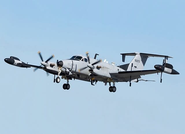
I often see Army RC/UC/EC-12s flying around with a ridiculous number of antennas and internal equipment installs. I'm sure these aircraft are built with considerations for all these installed/future mods [penetrations, masses, aero-loads... all-over] in-mind.

RC-12_x69u0d.jpg


Just thinking-out-loud for future consideration.

Regards, Wil Taylor
o Trust - But Verify!
o For those who believe, no proof is required; for those who cannot believe, no proof is possible. [variation, Stuart Chase]
o Unfortunately, in science what You 'believe' is irrelevant. ["Orion", HBA forum]
o Only fools and charlatans know everything and understand everything." -Anton Chekhov
 
Dont want to drag this topic away ..
- Back in my apprentice days ..
Great Firewall Design! Great Engine Design !
but has anyone looked into how we gonna replace the magneto ????
 
Nope, when the first (or second or third) weight crisis hits in a new airplane development program (and it will occur in EVERY program at some point) all of the design for manufacturability and design for repair and design for future modification "nice to have" stuff gets thrown right out the window in order to meet the weight target that has been promised to the customers. Have seen it happen many many times.
 
yes Will, often OEMs account for future antennas ... eg on the DHC8 most of the lower CL is double thickness skin. An OEM installing an antenna will generally make the local area double thickness. But remember the OEM is focused on the weight of the plane as it leaves the factory, adding utility to the design is "nice to have" and usually of little value. And typically upper and lower CLs usually have stringers ... just for the fun of modifying the plane later !?

"Hoffen wir mal, dass alles gut geht !"
General Paulus, Nov 1942, outside Stalingrad after the launch of Operation Uranus.
 
Maybe I'm missing something, but... why do the fasteners need to be countersunk? Are there specific aero requirements at play? Any reason you couldn't just use a protruding head rivets?

Seems like the main concern at the top of the thread was avoiding knife-edging. Can't you just install an internal doubler and MS20470 universal head rivets? If you're picking up existing countersink locations just install countersink repair washers.

By the way, your "Option 3" sounds like a pretty common industry practice called "microshaving". Don't know if I'd recommend it if avoidable but it's definitely done and I'm sure you can find some literature on it. FYI:

thread2-76190
thread2-102050

Keep em' Flying
//Fight Corrosion!
 
Clever,
I just inferred from the OP's statement that the customer forbade an external doubler... that using protruding rivets would be forbidden too. Check all assumptions!
 
and under the foot print of the antenna (as the rivets primary job is to unload the skin at the hole.

a 0.7" hole unreinforced is untraditional but shouldn't be a real problem (at least it is easy to analyze). In any case you could go back to the customer ... without an external dblr this is your inspection program, with it (the dblr) the intervals are longer ... pick one.

"Hoffen wir mal, dass alles gut geht !"
General Paulus, Nov 1942, outside Stalingrad after the launch of Operation Uranus.
 
I feel good about this ..
Planning an internal stiffener/channel that will pick up at frames either end and only have the 2X antenna mounting screws pass through the skin into the channel. channel will be spaced with a Teflon gasket to prevent chaffing. Channel will support support antenna aero & side loads. Beauty is no (knife-edge) fasteners passing thru the skin. Only issue is the open hole - but this is not a major concession. I will bond a metal-metal Doubler for added security (& more peaceful sleep) - but will not take take any 'credit' for it in the analysis - thus avoiding any testing. Minor concern is moisture wicking between the metal-metal bond.
This is an executive aircraft - with relatively low cycling.
- Again - appreciate the communal input .. in putting this plan together.
 
you could fillet seal the edge of the hole ... seal in edge of the dblr ... or an alligator grommet ?

But I dislike adding stuff for no credit (even tho' I do that "conservatively neglect the dblr"). Do your DTA, be conservative, and annual visual inspection shouldn't be a problem.

I sense you're in the US ... how do you guys treat limitations ? For us (up here in Canada) they need to be approved (stamped and signed) by TC.

"Hoffen wir mal, dass alles gut geht !"
General Paulus, Nov 1942, outside Stalingrad after the launch of Operation Uranus.
 
rb1957 ..
Fellow SAIT AET grad (1996). Haha
North country as well.
 
Status
Not open for further replies.

Part and Inventory Search

Sponsor