Continue to Site

Eng-Tips is the largest engineering community on the Internet

Intelligent Work Forums for Engineering Professionals

  • Congratulations KootK on being selected by the Eng-Tips community for having the most helpful posts in the forums last week. Way to Go!

How to Calculate the Diameter of a Grooved Bar considering Torsion 1

Status
Not open for further replies.

Jungyong Ko

Mechanical
May 12, 2024
2
Hi all,

I need help calculating the diameter of a bar with a groove, as shown in the attached diagram. I am designing a coupler to connect a valve and an actuator following ISO 5211.
I want to find out the shear stress based on the torque that passes through the coupler. However, the cross-section of the coupler is not a simple circle or rectangle but a shape with a cut-out in the middle, which makes the calculation difficult.
Because I don't know how to calculate the shear stress, I also can't find the correct diameter.
Can someone explain how to calculate the shear stress or diameter for this shape? Any methods or resources would be very helpful.
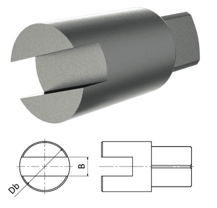
coupler_ddrbsq.png
 
Replies continue below

Recommended for you

If you want an accurate answer a good FEA model might work, although since the loading is a contact problem it won't be esay.

Roughly speaking the loading will be a 'tangential' force along one edge of the groove on each half of the remaining material, although its distribution will also depend on the properties of the tongue that engages with it.

As such I don't think you can really approach this as classical torsion problem.

The prying action of the tongue in the groove needs thinking about as does the stress raiser at the end of the groove.


Cheers

Greg Locock


New here? Try reading these, they might help FAQ731-376
 
One of the tangs can be looked at as a cantilever. From contact loading on one of the flat faces, you can assume an appropriate load distribution, zero in the middle of the contract edge and changing towards the outer surface. This loading will apply shear, torsion and bending. I expect you will need to assess the shear at the end of the tang, local to where the load is applied, and at the base of the tang, where you’ll have kt factored bending and torsional shear.

Thinking on the contact distribution, going from the middle of the contact edge to the outer surface, you could assume zero in the middle and changing by a function of linearly increasing distance, the tang thickness (1 in the middle, zero at the end), and the shear direction component (1 at contact line & angular change to becoming parallel with outer surface). This will generate a more conservative distribution compared to triangular. It can be solved by equating torque due to shear with the applied torque.
 
This is an interesting problem. It's unique.
This reminds me of a straight slot head screw head.slot.
Problem is it is very weak design and is subject to plastic deformation.
I would suggest a different more robust design.
Unless this for a very light load.
What ever the Calc is I would double the size.
Better there is more robust coupling designs.
 
As said, this is an interesting problem and it got me thinking. Attached is the initial thoughts I had on the applied loading and resultant shear stress local to the free edge of a tang, the other seeing equal and opposite. Obviously, due to the complexities of the problem, any hand analysis approach should be considered conservative. It’s a difficult one, but this approach may give you some ideas.
 
 https://files.engineering.com/getfile.aspx?folder=62e2532a-d391-4ec4-9a86-89d0cbe6cd86&file=Groove.pdf
It's basically one face of an Oldham coupling.

So there must be a solution somewhere.
 
I would use the approach of rectangular tangs.
I would purchase over sized Round. Mill the ends
To rectangular. Then slot it. I would use torsional stress calc.again this is not a great design.
 
Status
Not open for further replies.

Part and Inventory Search

Sponsor