Continue to Site

Eng-Tips is the largest engineering community on the Internet

Intelligent Work Forums for Engineering Professionals

  • Congratulations IDS on being selected by the Eng-Tips community for having the most helpful posts in the forums last week. Way to Go!

Cracks on pier cap

Status
Not open for further replies.

tmalik3156

Structural
Jun 21, 2021
97
Good day.

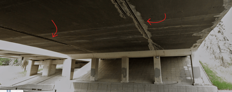
This is an unusual type of bridge (constructed in the '50s) where pier columns directly carry thrust from the deck slab - without any bearings in between. The photo below also shows a lot of leakage, efflorescence, corrosion at the soffit above.
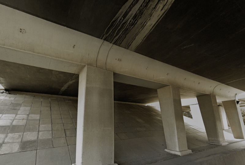
P1_ootcvr.png


There are cracks visible on pier cap. We are wondering about the reasons for these cracks.
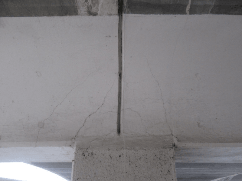
P2_qjjpp0.png


Our opinion is that these are not structural cracks. This is because the cracks would have spread in the opposite direction if they were due to punching shear. But we are not sure what the reason is. Are these shrinkage cracks?

The reinforcement drawing is shown below:
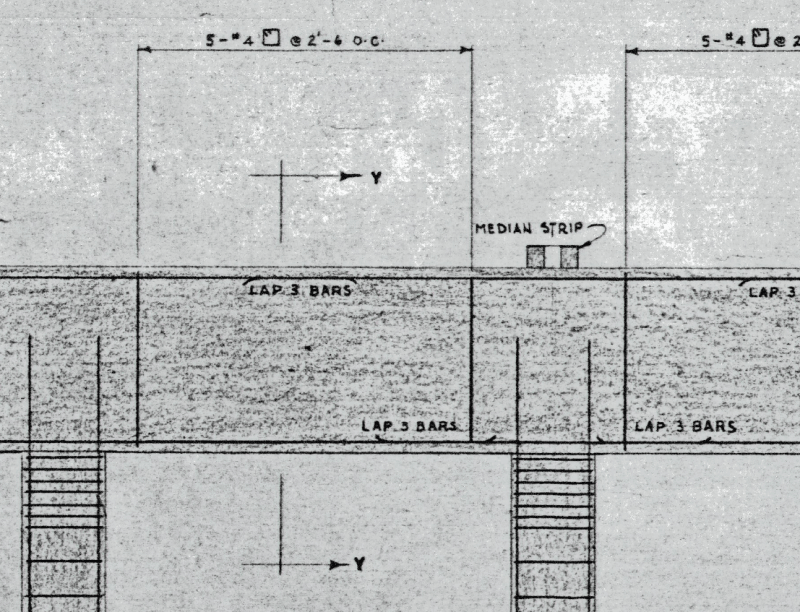
P3_tahwx2.png


Your opinions are appreciated. Thank you.
 
Replies continue below

Recommended for you

They look structural to me, possibly caused by shear.

Assuming that's an expansion joint in the girder over the column, the cracks could be from restraint of the girder, even by just friction.
 
I agree with Bridgesmith. In the 1983 AASHTO, the shear values were lowered quite a bit. Also, the photo doesn't match the drawing. Is there an expansion joint present?
 
Thank you BridgeSmith and bridgebuster for your comments.

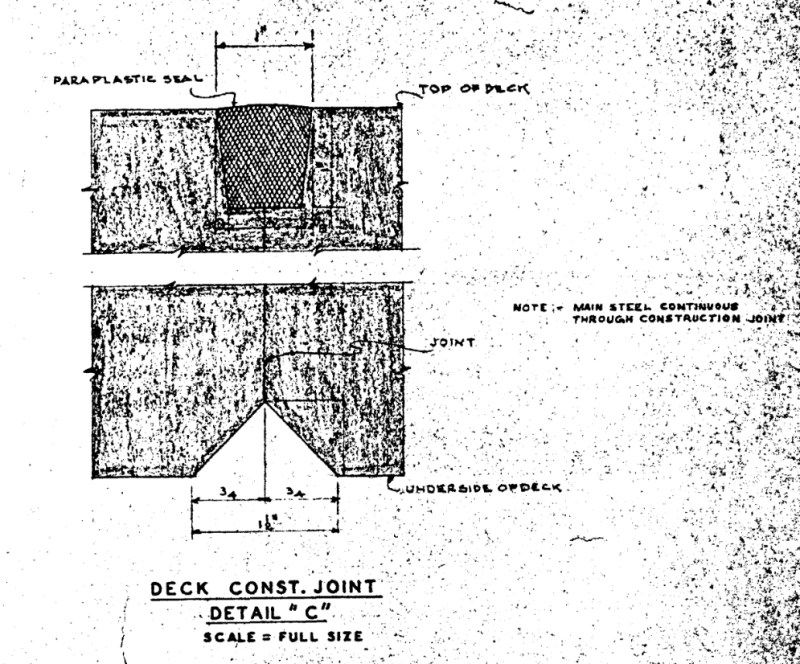
There are two longitudinal construction joints on the deck soffit. This is just a triangular groove that does not extend to deck top. Photo and drawings shown below. There are no other expansion joints on the bridge.

P4_s6dhju.png


P5_nfwvua.png
 
Crack pattern looks like a local crushing / shear failure. Not something to ignore.
 
I would say restraint complicated by lack of development of the bottom reinforcement into the connection.

There appears to be some vertical separation across the joint in the second photo!
 
That design isn't just unusual, it seems to be poorly detailed relative to the design concept.

Those deck construction joints seem to be letting a lot of water through. Given those construction joints are directly above beam expansion joints, I would expect the construction joints to also try to separate (drying shrinkage), even if the deck reinforcement is continuous.

The drawings don't seem to show how any reinforcement terminates at the expansion joints, which is annoying. Given the tops of the columns have lots of links and the longitudinal steel continues into the beams, there is probably a lot of beam restraint.

My guess is that the cracking is primarily the result of excessive restraint but complicated by shear. The multiple cracks curving around the top of the column is a bit of a concern. I can't really tell if the position of those curving cracks is linked to the change in beam width through its depth.
 
Thank you all for your valuable comments.
We will primarily point to the restraint against shrinkage as the primary reason for the cracks. We think the vertical groove was meant to control the cracks, but it obviously is not working.
We think the cracks are not due to shear. If it had been due to the shear / punching shear, we would have seen the cracks spreading outward rather than inward.
We will suggest repairing these cracks with epoxy crack filler.
 
The craks are apparently a structural (shear) due to almost complete lack of shear reiforcement in the pile cap. The #4 stirrups at 30" o.c. look inadequate. Applying expoxy filler is pointless, as this is cosmetic repair only.
Are the same cracks at the other face of the plie cap?
 
Status
Not open for further replies.

Part and Inventory Search

Sponsor