Continue to Site

Eng-Tips is the largest engineering community on the Internet

Intelligent Work Forums for Engineering Professionals

  • Congratulations KootK on being selected by the Eng-Tips community for having the most helpful posts in the forums last week. Way to Go!

Waste Water Gravity Flow Line Sizing 1

Status
Not open for further replies.

Pavan Kumar

Chemical
Aug 27, 2019
338
Hi All,

I am tasked to size the overflow line from tank. The line, that is supposed to be sized, comes out from the side outlet has a near horizontal run of 14 ft before it turns 90 degree down and travels 15 ft down and then turns horizontal ( 12 ft run) and connects to main header which is always liquid full. Process data is as below.
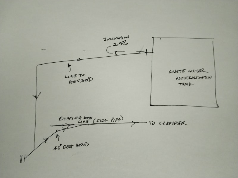
IMG_20240725_190517_xyjfgt.jpg


Flow Rate = 3300 gpm
Fluid = water
Temp = 20 Deg C
Density = 62.3160 lb/ft3
Viscosity = 1 cP
Incline = 2.5 %
Pipe fill = 1/2 full
Pipe roughness = 0.0018 inches

I am trying to use the eqn (5) in PD Hills Paper to calculate velocity

VL = (32g*m*i)^(1/2) * Log{ [(e/(14.8m)] + [0.22 u/ (m(g*m*i)^1/2)]}

where
g= gravitational constant in consistent units.
m = hydraulic mean depth = Flow Area / wetted perimeter
i = inclination
e = pipe roughness
u = kinematic viscosity, in consistent units.

I set-up an excel calculation sheet, however I am getting velocity as negative. I am trying to find out what is going wrong and need help here. Also I want to test this formula using the curve given in Fig 3 of PD Hills paper. My reason for using this equation, as opposed to using the curves, is to try different slopes and different liquid depths in the pipe.

Any help will be great help to me.

Thanks and Regards,
Pavan Kumar


Replies continue below

Recommended for you

OP,
Just from a quick read, I think you need to do this in metric (need log(x>1), also, I think roughness, being a coefficient with stay in its native form. I'd set it up and run some of the numbers from the curve to see if it works.

Edit: Attached the paper referenced.

 
Hi,
Review your calculation based on this note
Make sure you don't mix up the units, be consistent with your choice.
In the formula (pdf) for velocity mean, it appears g and gn , are they the same?
I've attached a .doc from Art Montemayor with some correlation (flow vs diameter @ different heights of liquid)
Good luck
Pierre
 
Hills' equation 5 for V[sub]L[/sub] should have a minus sign at the front. So your answers are correct if you disregard the minus sign in your answer (or multiply by -1).

There is a better description of this formula in an article by Gerard Hawkins titled "Overflows and Gravity Drainage Systems". It you search online for the combination of author and title you should find a copy. In this version Hawkins makes it clear that the answer would be negative. This article is so similar to Hills' version (equations and graphics) that I suspect that he was criticized for copying and has withdrawn it from his own web page, but there are still copies floating around the internet.

Katmar Software - AioFlo Pipe Hydraulics

"An undefined problem has an infinite number of solutions"
 
Why are you trying to calculate velocity?

As that paper says there is an acceleration element which results in a higher % full [EDIT] at the inlet as the flow increases in velocity up to the steady state velocity then the % full goes down. You don't want to end up with a full pipe at the inlet. There must be space for air to balance out at the inlet.

Also 3300 gpm looks to be off the scale of the graph at 750m3/hr. That's really quite a big pipe.

Overflow calcs like this are very common so it looks to me like you're trying to complicate life, but note your vertical pipe might need to be bigger to avoid getting into two phase flow. Look up Froude number...

[EDIT] - why are you trying to nickel and dime this? Just stick in a 20 or 24" pipe and be done with it. Get it wrong or a bit of dirt or birds nest and all of a sudden your overflow isn't working....

Remember - More details = better answers
Also: If you get a response it's polite to respond to it.
 
@LittleInch - Any acceleration in the sloped pipe will result in a lower % full as the velocity increases. You are correct to highlight the problem of entrainment in the vertical section. 14"NB is way too small. Air carried down this pipe will reduce the carrying capacity of the existing pipe to the clarifier. The runs are all short so I would be inclined to make it all at least 24" ID (not NB).

I did not see any mention of the pressure where the new line will enter the existing line. This should at least be noted to ensure that the static head that can develop in the vertical section can overcome this pressure.

Katmar Software - AioFlo Pipe Hydraulics

"An undefined problem has an infinite number of solutions"
 
Katmar,

That's what I meant to say only badly so I've edited it a bit.

Remember - More details = better answers
Also: If you get a response it's polite to respond to it.
 
Hi Harvey,

katmar said:
@LittleInch - Any acceleration in the sloped pipe will result in a lower % full as the velocity increases. You are correct to highlight the problem of entrainment in the vertical section. 14"NB is way too small. Air carried down this pipe will reduce the carrying capacity of the existing pipe to the clarifier. The runs are all short so I would be inclined to make it all at least 24" ID (not NB).

I did not see any mention of the pressure where the new line will enter the existing line. This should at least be noted to ensure that the static head that can develop in the vertical section can overcome this pressure.

Thank you for solving the negative velocity issue.

(i) If I calculate the line using JL*<0.3 then I see that I would need a 26" line. But if consider established flow the line size required is 14" Sch 80 for 3/4 full pipe. So oveflow line would be 26" or 14" then?. The client wants to use CPVC Sch 80 pipe and does not want to use Steel pipe. I got this using the Velocity equation. Also in Page 114 (last page) P.D. Hills says that coming of the side of the vessel the line should be sized for JL*=0.3 and use this line size for at least 10 pipe diameters. So 10 pipe diameters of 26" would be 260" or 21.6 ft. The horizontal portion of the line is only 14 feet long. So for my case I use 26" size which I am getting and use it for the vertical section also.

(ii) The existing line to which the new line is 14" and goes all the way to the clarifier. There is a 8 ft long vertical riser pipe in the Clarifier through which the waste water discharges into the clarifier. So the existing line is always liquid full. When Waste water goes from 26" to 14" pipe the water will start backing up until gets enough head to overcome the static and friction Head losses. This might mean the liquid backing into the Tank T-1 also (see attached sketch). Also the connecting tank nozzle is only 12". Would it be better to size the line for flooded flow then?.

Thanks and Regards,
Pavan Kumar


 https://files.engineering.com/getfile.aspx?folder=4907e398-ab67-4279-b562-5b5fe78c1528&file=Flow_Schematic.pdf
(i) The reason for using 10 diameters downstream of the overflow nozzle is exactly what LittleInch was describing. It takes some distance for the water to accelerate to the steady state velocity. The 26" overflow is required to overcome the entrance loss and provide this acceleration.

(ii) [EDIT: This calculation is wrong. See my later post below.] The line to the clarifier would be 136 ft long and by my calculation it would need a head of about 12 ft to overcome the friction in a 14" line. Your sketch does not show the level in the clarifier but it must be at least 8 ft (i.e. riser height), making the head available 6 ft at most. And that is without adding any allowance for solids in the water. So it should be overflowing already. Unless there is a lot of head space in T-1 I can't see this working, even in flooded mode.

Katmar Software - AioFlo Pipe Hydraulics

"An undefined problem has an infinite number of solutions"
 
To keep NFr < 0.3, line size has to be DN600 at least. Line velocity = 0.75m/sec at DN600.
Agreed, what is max normal level in clarifier ?
And with long low point run operating at low velocity, it is likely to bung up with solids and corrosion debris.
 
The pressure drop I calculated in paragraph (ii) of my previous post was wrong. I must have set my units wrongly somewhere. Sorry about that.

I was checking on George's calculations to see what the pressure drop would be if the entire line was replaced with DN600 pipe and that turned out to be extremely low. My next step was to reduce the pipe ID until the pressure drop reached 2 ft. This indicated the an ID of 12.3" would give a pressure drop of 2 ft in the 116 ft of pipe to the clarifier and showed that my previous calculation was wrong. I should have realized that I had made a mistake as this is an existing line that is presumably operating correctly.

It is only the section of pipe from the overflow of T-1 to the bottom of the vertical section that needs to be designed using Hills' formulas. The horizontal line to the clarifier can remain 14" with a velocity of 8.6 ft/s (2.6m/s) and this will help with the transport of solids to the clarifier.

Katmar Software - AioFlo Pipe Hydraulics

"An undefined problem has an infinite number of solutions"
 
Suspect this line wont be running full pelt at 3300gpm all the time. There will be times when flow is much less, and solids may settle in this long low point section. This whole line probably has to be rebuilt with a healthy continuous downslope towards the clarifier, else all calculations would be invalid.
 
Hi katmar,

katmar said:
The pressure drop I calculated in paragraph (ii) of my previous post was wrong. I must have set my units wrongly somewhere. Sorry about that.

I was checking on George's calculations to see what the pressure drop would be if the entire line was replaced with DN600 pipe and that turned out to be extremely low. My next step was to reduce the pipe ID until the pressure drop reached 2 ft. This indicated the an ID of 12.3" would give a pressure drop of 2 ft in the 116 ft of pipe to the clarifier and showed that my previous calculation was wrong. I should have realized that I had made a mistake as this is an existing line that is presumably operating correctly.

It is only the section of pipe from the overflow of T-1 to the bottom of the vertical section that needs to be designed using Hills' formulas. The horizontal line to the clarifier can remain 14" with a velocity of 8.6 ft/s (2.6m/s) and this will help with the transport of solids to the clarifier.

I presume you are calculating the pressure drop in 24" (DN 600) line assuming it to be full pipe. If not kindly let me know how you did it.

Per PD Hill's paper, the line should be sized for JL*<0.3 not NFr < 0.3. Though in this case they are both same. Also the piping used here is CPVC Sch 80. I get line size greater than 24" ( See attached calculations). Also, in today's meeting with the client I presented the options available.

Options Available:

1) Option-1: Use 26" line size for the Overflow line up and Tie-in to the 14" existing line to clarifier. This would require them to use HDPE or PVC Lined pipe as CPVC comes only until 24". Also they need to slope the horizontal run by 2.5% to achieve 3300 gpm flow rate.

2) Option-2: Use the 12",14" or 16" pipe for the new line and have the water flow as full pipe instead of partial pipe. My calculations using Bernoulli's equation showed that flow rates of 4354 gpm, 4483 gpm and 4532 gpm respectively possible due to the elevation difference between T-430 ( T-1 as noted previously) and Clarifier (T-460B). Please see the sketch pasted below.

[URL unfurl="true"]https://res.cloudinary.com/engineering-com/image/upload/v1722290280/tips/1717_001_lp12id.pdf[/url]

I have attached the calculation for 16" line done in excel. The above flow rates are from the same calculations done in AFT Fathom.

Due to very high flow rate, it looks like the Tank T-430 will never overflow ( Actual Flow rate > required flow rate). I want make sure the line will be flooded. Do I have to calculate the sealing flow rate to keep the pipe flooded?.

The client is leaning to Option-2 as (1) They don't line size as big as 26" that too of HDPE / Lined Pipe and 2) Sloping the line from a straight flange of the tank overflow nozzle would need flexible joints etc.


Thanks and Regards,
Pavan Kumar


Yes, I was calculating the 24" line proposed by George as running full. George's first post has disappeared so I cannot verify now what he was actually proposing.

The 16" line will work provided it is flooded but this is hard to maintain. What happens in practice is that as the tank fills up it starts overflowing into the outlet. Initially the head will be insufficient to provide the full flow and the level in the tank will keep rising. When the overflow is almost flooded it will start pulling air with the water and this will cause 2-phase flow and the pressure drop will increase to beyond what you have calculated.

The level in the tank keeps rising and will eventually seal the overflow outlet and prevent more air being entrained. The pressure drop through the line is still higher than expected because there will still be some air in the line but gradually all the air will be flushed out. At this point the head available from the level in the tank will be more than is necessary for the target single phase flowrate and the flow will increase to above the target. This pulls the level in the tank down to a level where air is drawn into the outlet again and the cycle starts all over again. This is somewhat similar to the situation shown in Hills Fig 1.

When the line is running full you will get the benefit of the syphon effect as the water runs down to the lower level. But until the line fills up you do not get this benefit. Imagine the situation where you have your 12" outlet not connected to any piping and it is simply discharging to atmosphere. In this case the head in the tank has to overcome the entrance losses into the nozzle, but it must also provide the energy to accelerate the water (as per Bernoulli). If it were simply discharging to atmosphere this velocity head for 4182 gpm out of a 12" nozzle would be 2.6 ft of water and this is what could happen every time the syphon is broken in the piping by air being entrained. This head must be added to the entrance losses. You would probably not lose the full syphon effect and the increase in level would be less than this but I have seen tanks operating in this cyclical manner continuously.

Provided there is sufficient height in the tank above the outlet it can run like this without problems if the cyclical surging does not impact the process. The actual maximum and minimum levels in the tank are hard to predict. It is when steady predictable flow is necessary that solutions like those proposed by Hills are used.

If you do decide to use the Hills approach and you cannot obtain 26" piping you could provide multiple smaller outlets, or a custom made rectangular outlet. This would have the additional benefit of controlling the level over a narrower range.

Katmar Software - AioFlo Pipe Hydraulics

"An undefined problem has an infinite number of solutions"
 
The other way if you want to use the smaller line is to put in a vent pipe at the junction between the slightly sloping pipe and the vertical riser down to the 14" line? This is simialr to the current situation where the pipe simply empties into a vapour space in the second tank.

This way as the flow increases the air has somewhere to go and doesn't need to go all the way to the clarifier.

When the inlet is fully submerged, this could still result in partial fill as the flow accelerates int he line and the vent will allow this without resulting in vacuum and gurgling or surging.

If the line becomes full all the way to the vent connection this should then also fill the vertical line, but if it doesn't then also allows air to vent out.

It would be best to route the vent line back into the tank to stop stray bubbles or water drops coming out of it, but so long as it is higher than the tank then it should be alright.

I'll leave it to my fellow posters to note other issues with this idea.


Remember - More details = better answers
Also: If you get a response it's polite to respond to it.
 
LittleInch's proposal will help greatly in preventing air from being drawn into the common piping (and affecting other processes connected to it). I have seen variations on this theme working well. There are two factors (that I can think of) that need to be taken into account with this set up.

The first is that having a vent there will hold the pressure at that point at atmospheric pressure and all the energy for accelerating the water into the overflow pipe must be provided by the level in the tank. When I have seen this arrangement work the pipe from the overflow to the vent has had a significant drop in elevation to provide this energy - which Crane TP410 calls the exit loss but that is not an accurate description. I suspect that some syphon effect is helping the current arrangement but I am not confident of the methods for predicting if the riser will run full and provide a syphon. I suspect a Froude Number of 2.0 or more will ensure that a vertical pipe in downflow will run full but this might be overkill.

The second is the problem of getting the vent to work when the overflow pipe runs full - as LittleInch has already pointed out. This can be overcome by designing the vertical riser to have a Froude Number of less than 0.3. This results in a large pipe for the section where the water flows but the actual vent can be much smaller.

Katmar Software - AioFlo Pipe Hydraulics

"An undefined problem has an infinite number of solutions"
 
Hi Katmar and LittleInch,

Thank you very much for explaining in detail how the overflow line works when it is running full with the corresponding level increase in T-430 until all the entrained air is flushed out and no more entrainment takes place. Yes this would lead to cycling for sure. However per Littleinch's note that using a smaller line ( that is 12" in our case, the client decided on 12" from a choice of 12",14" and 16"), we need a vent line to drive out all the entrained air, I have a few questions as noted below. The client wants 12" line for the horizontal and vertical run and then increase to 14" just before it connects to the existing 14" line.

katmar said:
LittleInch's proposal will help greatly in preventing air from being drawn into the common piping (and affecting other processes connected to it). I have seen variations on this theme working well. There are two factors (that I can think of) that need to be taken into account with this set up.

1. Will the overflow line entrain air even there is vent to drive out the air and will two-phase flow still not happen when the drive is being out. Will this not cause pressure drop to increase and reduce the flow capacity of the line?. How is this different from the situation when there is no vent line?.

2. You say that having a vent line greatly prevents the air from getting into the common 14" piping but what about the 12" overflow line itself as pointed in point no. 1 above?.

3. What would be the basis of sizing this vent line or what would be a minimum size that would work fine?.

katmar said:
The first is that having a vent there will hold the pressure at that point at atmospheric pressure and all the energy for accelerating the water into the overflow pipe must be provided by the level in the tank. When I have seen this arrangement work the pipe from the overflow to the vent has had a significant drop in elevation to provide this energy - which Crane TP410 calls the exit loss but that is not an accurate description. I suspect that some syphon effect is helping the current arrangement but I am not confident of the methods for predicting if the riser will run full and provide a syphon. I suspect a Froude Number of 2.0 or more will ensure that a vertical pipe in downflow will run full but this might be overkill.

In our case the we want the water level to be just above or at the 12" outlet nozzle. The tank top is just 3 ft above this nozzle. I used the elevation difference between the T-430 12" tank nozzle and the clarifier to calculate the flow rate using Bernoulli equation. The 12" line is NOT sloped so the pressure at the vent will be same as that at the nozzle inlet. The vertical riser will also be 12" so the vertical riser will also be flooded when the 12" tank nozzle is flooded, unless it entrains air from the vent line. Will this head pressure not sufficient to generate the flowrate I calculated?. I am bit concerned here if this 12" overflow line (including the vertical riser) will work with the vent line.

Your answers to clear my confusion will be of great help!.

Thanks and Regards,
Pavan Kumar.

 
The first question to answer is whether it is necessary to avoid air (and the consequent varying flow and pressure drop) in the common line to the clarifier. If having air in this line is not a problem then the solution you showed in your earlier sketch and calculation (i.e. 12" nozzle and 16" pipe to the junction with the existing 14") will have a good chance of working. The only risk is that when the level in the tank cycles it may come close to the top of the tank. Theoretically you will just make it but it would be closer to the edge than I would be comfortable with.

The more I think about LittleInch's vent system the more I like it, but a vent will not work if the vertical riser is 12" or 16". For air to be released from water in a vertical downflow leg the Fr No should be less than 0.3. For your 12" (11.3" ID) this would require the flow to be less than 510 gpm, and below 910 gpm for the 16". With a flow of 3300 gpm in a 16" line the bubbles will remain in the water and the vent will not help. In fact the vent will be detrimental because it will prevent the downleg from forming a syphon and helping draw the water out of the tank.

To get the vent to work with a flow of 3300 gpm the ID of the vertical leg must be at least 24". My recommendation would be to install a new 16" nozzle in T-430 and run a 16" line to a 24" ID vertical leg. This leg should extend upwards to about 2 ft above the top of T-430. The top should be closed with a 6" vent going up about 10 ft, and preferably discharging above T-430 in case there are some droplets carried over (See LittleInch's suggestion above). The bottom of the vertical leg can be connected to the existing 14" line using more 14" pipe. You would probably still get some cycling of the level in the tank but it will be only a few inches.

If your client wants to do this as cheaply as possible and is aware of the risks then try the design you sketched earlier. If it does not work then you can install the larger pipe and vent system.


Katmar Software - AioFlo Pipe Hydraulics

"An undefined problem has an infinite number of solutions"
 
Hi katmar,

katmar said:
The first question to answer is whether it is necessary to avoid air (and the consequent varying flow and pressure drop) in the common line to the clarifier. If having air in this line is not a problem then the solution you showed in your earlier sketch and calculation (i.e. 12" nozzle and 16" pipe to the junction with the existing 14") will have a good chance of working. The only risk is that when the level in the tank cycles it may come close to the top of the tank. Theoretically you will just make it but it would be closer to the edge than I would be comfortable with.

I don't think there is any issue process wise to entrain the air all the way to the clarifier, but I will check with the client. If there is no problem entraining air will air that is trapped in the water not create increased pressure drop in the existing 14" line that is nearly 120 ft long?.

katmar said:
The more I think about LittleInch's vent system the more I like it, but a vent will not work if the vertical riser is 12" or 16". For air to be released from water in a vertical downflow leg the Fr No should be less than 0.3. For your 12" (11.3" ID) this would require the flow to be less than 510 gpm, and below 910 gpm for the 16". With a flow of 3300 gpm in a 16" line the bubbles will remain in the water and the vent will not help. In fact the vent will be detrimental because it will prevent the downleg from forming a syphon and helping draw the water out of the tank.
Ok I understand.

katmar said:
To get the vent to work with a flow of 3300 gpm the ID of the vertical leg must be at least 24". My recommendation would be to install a new 16" nozzle in T-430 and run a 16" line to a 24" ID vertical leg. This leg should extend upwards to about 2 ft above the top of T-430. The top should be closed with a 6" vent going up about 10 ft, and preferably discharging above T-430 in case there are some droplets carried over (See LittleInch's suggestion above). The bottom of the vertical leg can be connected to the existing 14" line using more 14" pipe. You would probably still get some cycling of the level in the tank but it will be only a few inches.

Please explain how you got the 6" vent size and the vent line going 10 ft up.


Thanks and Regards,
Pavan Kumar
 
Folks, pls take note of the critical head requirement for overflow lines to flow liquid full shown in Fig 6-30 and eqn 6-137 in Perry 7th edn. Its not clear to me what L means in this context; I suspect it is the vertical drop in the overflow line, which in this case would be dependent on the liquid level in the clarifier.
@pavan should confirm if there are solids in this waste water stream, and / or if plant operations intend to rod out this long low point section regularly of solids as mitigation against partial blockage.
 
Status
Not open for further replies.

Part and Inventory Search

Sponsor