Hello,
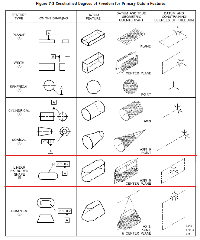
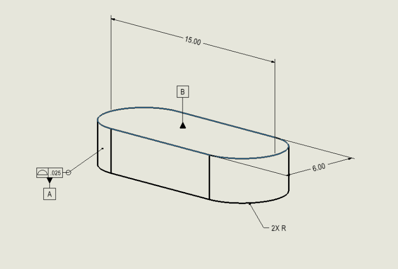
I have a part which has an outside profile of a straight slot. This part has a top surface and a bottom surface, and has additional machined features not shown in the example. My primary datum, A, is the outside surface of the part. This is similar to ASME Y14.5-2018 Figure 7-3(f), which constrains five DOF. The secondary datum is the top surface as seen below. This datum constrains the final DOF.

All of the additional machined features on this part are positioned with respect to this AB datum reference frame.

The problem I'm having is best described as the following:
I've tried to get around this issue by breaking up the surfaces in order to sort of create the center planes myself, but it this ends up resulting in bad inspection results that seem to conflict with reality. For this, I'll treat one radius as a cylinder (line for 4-dof), the other radius as a circle (point for 1-dof), then the top plane (1-dof). I think that due to the short height of the part and only being able to probe/scan half of each radius face (instead of a full cylinder/circle - hope this makes sense), so much "error" is introduced that it immediately makes the part seem as though it is out of tolerance.
Does anyone have a recommendation on what we can do in order to get this treated correctly by the software? I've tried to model the outside surface/profile as a single surface, but we ran into problems when we first tried that some time ago. We may give it another go, but haven't yet.
Thank you.
I have a part which has an outside profile of a straight slot. This part has a top surface and a bottom surface, and has additional machined features not shown in the example. My primary datum, A, is the outside surface of the part. This is similar to ASME Y14.5-2018 Figure 7-3(f), which constrains five DOF. The secondary datum is the top surface as seen below. This datum constrains the final DOF.

All of the additional machined features on this part are positioned with respect to this AB datum reference frame.

The problem I'm having is best described as the following:
My actual modeled part is comprised of five surfaces in the CAD program, SolidWorks. These surfaces are two radius surfaces, one large flat surface, and for some reason two smaller flat surfaces opposite the large flat surface. The CAM2 software does not seem to be able to recognize these five surfaces as being one surface which can then constrain five DOF.
I've tried to get around this issue by breaking up the surfaces in order to sort of create the center planes myself, but it this ends up resulting in bad inspection results that seem to conflict with reality. For this, I'll treat one radius as a cylinder (line for 4-dof), the other radius as a circle (point for 1-dof), then the top plane (1-dof). I think that due to the short height of the part and only being able to probe/scan half of each radius face (instead of a full cylinder/circle - hope this makes sense), so much "error" is introduced that it immediately makes the part seem as though it is out of tolerance.
Does anyone have a recommendation on what we can do in order to get this treated correctly by the software? I've tried to model the outside surface/profile as a single surface, but we ran into problems when we first tried that some time ago. We may give it another go, but haven't yet.
Thank you.
