Continue to Site

Eng-Tips is the largest engineering community on the Internet

Intelligent Work Forums for Engineering Professionals

  • Congratulations IDS on being selected by the Eng-Tips community for having the most helpful posts in the forums last week. Way to Go!

Calculation of Safety Valve Disc Area

Status
Not open for further replies.

ReubixSmooth30

Mechanical
Jul 31, 2024
6
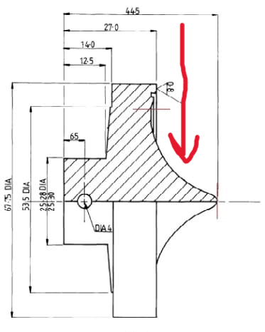
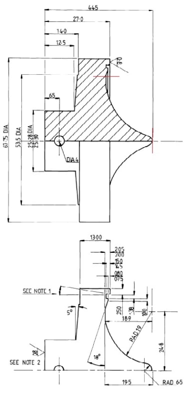
I am trying to find the area of the curved surface of the safety valve disc shown below (the area between the red lines). Is there a formula for this? I know from the manufacturer that the area is approximately 3372 mm^2, but I am not sure how they got this. Thanks!
Valve_Disc_hsv3qa.jpg
 
Replies continue below

Recommended for you

No red line appearing.

What is it you are trying to achieve from this?

*** Per ISO-4126, the generic term
'Safety Valve' is used regardless of application or design ***

*** 'Pressure-relief Valve' is the ASME/API used term ***
 
There are two red lines - a horizontal one and a vertical one in the top diagram. I am trying to have a generic method of calculating the valve disc area for when determining the lift achieved through Trevitesting.
 
If you are trying to calculate the force due to pressure acting on the disc to open the valve, it is pi D squared over 4, where D equals 53.5. Components of force in the vertical direction cancel each other and are unimportant.
 
Or are you trying to calculate back pressure (depends on PRV type)? If just R19 area is experiencing backpressure, then it's just normal forces so πR^2-π(R-19.5)^2=area where R=disk radius
 
No back pressure in this case, as the valve vents directly to atmosphere.

All I am trying to determine is how the manufacturer has obtained the value of the 'mean surface area' of the disc (which, as per the data sheet for this particular valve model, is 3372 mm^2). For when testing hydraulically in-situ, this surface area value is used to determine the amount of hydraulic force needed to unseat the valve given that the steam pressure is already 'helping' lift the valve.
 
It's the area inside the seal on the valve. Your drawing does not show where the disc contacts the seal.
 
Can you share the manufacture cutsheet? I am having difficulty understanding how the area you are seeking has anything to do with lifting force. As Compositepro said, the lifting force would be a result of the disk area.
 
Unfortunately, I don't have the manufacturer cutsheet. The sectional view of the disc in the diagram I provided is all I have. I'll try and explain it a bit better.

In the diagram in my original post, the curve bounded by the red lines (i.e. the hatched part of the cutaway section) is one side of the disc (which is symmetrical). This is the surface that is exposed to steam pressure when in service. I need to know the value of the disc area to determine how much force the steam provides when acting at normal operating pressure.

The manufacturer has provided the disc area which is all well and good, but I want to know HOW they found this area. Is it as simple as (pi*D^2)/4, where 'D' is the diameter of the disc exposed to the steam? Or, do they take into account the height and curvature of the raised 'knub' or 'nipple' which increases the surface area of the disc relative to a purely flat disc.
 
It is going to be the area exposed in the direction of lifting, so the mean area. Just confirming, are you saying the side exposed to the steam pressure is as shown?
lkj034hx_npqkxc.png
 
It will be the exposed area normal to the lifting direction, exposed to the steam.
Is it as simple as (pi*D^2)/4, where 'D' is the diameter of the disc exposed to the steam
Essentially yes, if you have the dimensional data to determine that, which you should. Pressure will act in all directions, it only the direction normal to the lifting force that would be of concern.

Edit: I still do not understand this valve design. Even a manufacture and model number would help. I just like to know anything I provide is as correct as possible but based on the information given, I think what I have said is appropriate.
 
You say you are trying to calculate for the purpose of 'Trevitesting'.

Trevitesting is the trade name of the 'in-situ' testing of Pressure-relief Valves by devices made only and licensed by the company Furmanite.

The generic term is In-Situ Testing.

For In-Situ Testing, it is the nozzle seat pressure area that is necessary to to know, in order to determine the set pressure result from a in-situ test.

The nozzle seat pressure area is generally smaller than the disc seat area. This is standard design of pressure-relief Valves - the spring load of the valve is concentrated from the disc seat area to the smaller nozzle seat area, and that's why the nozzle pressure area is used.

Pressure-relief Valve manufacturers are often asked to document the actual, as measured outside and inside diameters of the nozzle seat. In the past we used to record these measurements on the test certificate for users convenience for when they wanted to do in-situ testing. Each one was recorded as it was insufficient to take the manufacturing drawing sizes, which has tolerances, and could make a small difference.

Your manufacturer has probably given you the nozzle seat area.

Note also that regardless of what the in-situ test device salesman tells you, you cannot determine lift and blowdown from in-situ testing. Yes, it produces a nice graphical report that shows this, but this is artificial as the system has itself not gone into overpressure, against which the stand alone valve would react accordingly (achieving its certified lift and expected blowdown/closing). In-situ testing is verifying expected set pressure only.

Note that there is a separate safety/relief valve forum on eng-tips.


*** Per ISO-4126, the generic term
'Safety Valve' is used regardless of application or design ***

*** 'Pressure-relief Valve' is the ASME/API used term ***
 
The red line you drew is not going to represent the seat area for the relief pressure calculation.

From an "approximate" 3372 mm^2 area, you can calculate the effective seal diameter as being "approx." 65.52 mm. The o.d. of the disk on your drawing is shown at 67.5 mm, so a 65.5 mm diameter is outboard of the inner edge of the 2.50 wide step feature on the rim of the disk, i.e. within about 1mm of the outer rim edge.
 
Status
Not open for further replies.

Part and Inventory Search

Sponsor