Continue to Site

Eng-Tips is the largest engineering community on the Internet

Intelligent Work Forums for Engineering Professionals

  • Congratulations KootK on being selected by the Eng-Tips community for having the most helpful posts in the forums last week. Way to Go!

GD & T

Status
Not open for further replies.

maggie12

Student
Aug 19, 2024
2
Hello,

I have a few questions and appreciate your assistance. I was wondering if:

1. The drawing below is complete.
2. Are the positions of the three holes on the left completely defined? Or do I need to define a third datum?
3. Do I need to put all the dimensions into a square (make them basic dimensions)?
4. How is the position of Datum B (in x and y directions) defined?
5. How do you put gd&t on threads of a screws hole? The threads are non-conventional.
6. What happens if hole B is called out through profile tolerance?

Thanks very much!
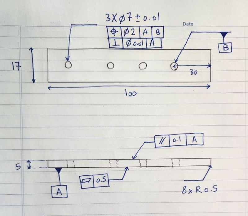
drawing_xduzep.jpg
 
Replies continue below

Recommended for you

You don't put "GD&T" on anything. "GD&T" was marketing for ANSI Y14.5 Dimensioning and Tolerncing back in the 1960s and it has stuck like stink.

If you wish to use "geometric characteristic tolerancing", such as position tolerance you need to decide what the important features are to be used as datum references and datum feature symbols to identify those references.

1. The drawing below is complete.
1A - The drawing does not appear to be complete. The ways in which it is incomplete depend on what dimensioning and tolerancing solution you have for the design intent of the use of the part.

2. Are the positions of the three holes on the left completely defined?
2A - There is no vertical or horizontal control on their basic dimensions

2a. Or do I need to define a third datum?
2aA - Probably. The perimeter of the part isn't entirely limited in its location or orientation relative to the positioned holes. One could use any of a number of strategies to use part of the perimeter as a datum feature or uses the holes as a datum feature to limit the perimeter. Usually this choice is based on what holds the part in place in use. Example: On a head gasket for an engine there are usually two pins that are used - one fitting a precise hole and the other fitting a precision width slot in the gasket. Obviously the face of the gasket is the primary interface. All other features on the gasket are given position or profile tolerances relative to the face, hole, and slot width.

3. Do I need to put all the dimensions into a square (make them basic dimensions)?
3A - It depends. A basic dimension symbol, the rectangle around the dimension value, is often used, though a general note that "dimensions without direct tolerance are BASIC" is also used.

4. How is the position of Datum B (in x and y directions) defined?
4A - That depends - see 2A. One could use that hole as a datum feature to support the tolerance on the perimeter. In that case adding a perpendicularity tolerance would suffice. Otherwise you need to decide what perimeter feature is suitable as a datum feature for limiting the movement in the vertical direction and what perimeter feature is suitable as a datum feature for limiting the movement in the horizontal direction.

5. How do you put gd&t on threads of a screws hole? The threads are non-conventional.
5A - You put a Feature Control Frame, FCF, on a threaded hole just like any other hole. Typically a perpendicularity or position characteristic would be used. The default interpretation is that the pitch diameter is the surface being controlled, but you can specify that the geometric characteristic tolerance applies to the Minor or Major diameter.

6. What happens if hole B is called out through profile tolerance?
6A - You might get a phone call from either the inspection department or the machine shop asking why a hole has a profile tolerance. Practically? It depends on what the part is intended to do.

---

The general answers to Dimensioning and Tolerancing questions or, more specifically, geometric characteristic tolerances, are best viewed in a manner similar to solving computer programming problems. Datum Features are usually constants for equations; the FCFs are the equations that use them. The results of those equations are the range of possible solutions, which is unlike most computer programs. Sometimes, when (M) or (L) is used in datum references, the Datum Features are also ranges of values, which is referred to as Datum Shift.

This "range of solutions" makes understanding a bit more difficult, because the possible answers aren't usually single numbers, though the limits to the ranges can be. For example, a hole with a direct tolerance can have any of an infinite number of sizes. It can have only one minimum size and, with the envelope principle, that minimum size will fit a perfectly straight rod or pin. If there is a position tolerance applied, the virtual size of a perfect rod or pin perfectly located and oriented to the datum references will the the minimum size of the hole minus the position tolerance.

In manufacturing the tolerance results usually have some statistical distribution, often the Normal Distribution, and are controlled with statistics and analyzed with probability - the branches of mathematics that deal with problems and their solutions that involve ranges.

It's up to the user to decide which features will be the basis of these computations and what computations need to be made, just like programming. There aren't specific answers, though there are some common solutions to the various mechanical engineering problems, such as the gasket example above.
 
maggie12,

Your datum scheme does not control rotation.

It looks to me like you have four 7mm holes. If you apply the datum[ ]B to the complete pattern, you control rotation. This is common practice. If you apply a positional tolerance to the pattern with respect to datum feature[ ]A, you control the pattern. You can use a profile tolerance to control the outline from datum features[ ]A and[ ]B.

If you apply a positional tolerance to a set of tapped holes, I can easily measure to the minor diameters. These ought to be fairly concentric to the pitch and major diameters, so you should be okay. Thread gauges measure pitch diameters. You can screw in the no-go gauge and measure to that if it really matters. I have never worried about this.

My basic, idiot level test for drawings is inspectability. If there is a way to inspect your part and verify it is functional, your drawing is good.


--
JHG
 
Thank you both very much.
@drawoh, could you please kindly show it on an image, if possible? I have a hard time imagining the datum applied to the pattern.
I will appreciate it if you add whatever that might be missing, to make the drawing complete.

Thanks again for your time and explanation.
 
Status
Not open for further replies.

Part and Inventory Search

Sponsor