Continue to Site

Eng-Tips is the largest engineering community on the Internet

Intelligent Work Forums for Engineering Professionals

  • Congratulations KootK on being selected by the Eng-Tips community for having the most helpful posts in the forums last week. Way to Go!

how to properly use the centerpoint of a specific circular section of a hole as a Datum

Status
Not open for further replies.

Blue33

Mechanical
Oct 22, 2018
6
I keep running into these situations where the engineers want to designate a datum target point at a section of a hole. Say the hole is 1 inch deep, at .500 inches they want to use the centerpoint of that section as a datum target point. I can't seem to wrap my head around how this point actually constrains the part. In one of these situations, I have a planar face (primary datum) and then two holes that are perpendicular to the face. If I define one of these centerpoints in each hole, do I fully constrain all 6 degrees of freedom? I'm trying to encourage them to use the centerline of each hole as the secondary and tertiary datum because I know that works, but they don't want to do that.

Am I actually defining a spherical datum feature at each of these points?

Is using a "circular target line" a proper way to call out this case as well? the minimal content in Y14.5 2009/2018 doesn't give much guidance on how to use a CTL.

appreciate any help
 
Replies continue below

Recommended for you

From what I am gathering, the feature itself will not be spherical; the resolution will be a point at the center of the circle at a specific depth. The variation from that point is only going to lie in that plane that is parallel to the primary face and will be a planar circular areas.

It sounds like a simulation where, instead of bolts or rods, this is seeing knife-edge mating parts, something like a common engine valve, but sharper edged and fully inserted with a slight interference to just barely touching fit, sent down the hole.

A target line that is a circle is fine, I suppose, given that there isn't a description of what the part does or how it interacts with other parts.

If a plane and two bolts would keep the part aligned then a plane and two circular items jammed in the holes will do the same.

Edit: Technically, the contact is with the curve, which is the datum target; datum target are things that contact the surface or are tied to contact with the surface. There's a big opportunity right there for the well, accullally comments that don't need to be part of this.

The center is just the center of the circular target line (circle, in this case) and not an independent datum target point.
 
Blue said:
Is using a "circular target line" a proper way to call out this case as well? the minimal content in Y14.5 2009/2018 doesn't give much guidance on how to use a CTL

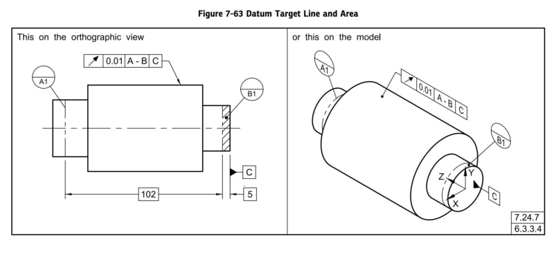
A circular datum target on a cylindrical feature is supported.
The following example from Y14.5-2018 is for an external cylinder but the same could be applied to holes of course.

Screenshot_20240829_213250_Drive_l9swak.jpg


And yes, one planar surface as the primary datum feature and 2 datum target circles inside holes that are normal to that surface as secondary and tertiary datum references would constrain all 6 DOF.
 
Status
Not open for further replies.

Part and Inventory Search

Sponsor