Continue to Site

Eng-Tips is the largest engineering community on the Internet

Intelligent Work Forums for Engineering Professionals

  • Congratulations KootK on being selected by the Eng-Tips community for having the most helpful posts in the forums last week. Way to Go!

Underground protective pipe calculation 1

Status
Not open for further replies.

Djidji444

Structural
Mar 11, 2024
17
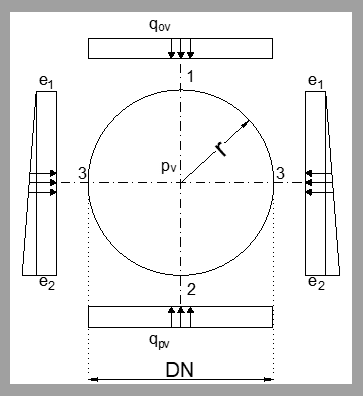
Does anyone have calculation formulas for how to calculate moments and forces per meter for a pipe loaded like this(as in the picture below), which is actually a buried protection pipe of an oil pipeline?
11111111_tgtvbm.png

In other words, how to calculate stresses and thus determine whether the adopted thickness of the protection pipe is okay?

Thanks in advance :)
 
Replies continue below

Recommended for you

Roark's Formulas for Stress and Strain should have the relevant formulas for cicrular rings. In the 7th edition, it looks like you'd want table 9.2, cases 10 and 11. You'll have to use superposition and be careful with your coordinate systems, but I think those should work.
 
While Roark has many common stress analysis formulas, using them for designing an oil pipeline is not appropriate.

External loads on a buried pipe combine with internal pressures and thermal expansion stresses resulting in complex stresses in a pipe, such stresses being limited by pipeline design codes. There are around 20 popular common pipe and pipeline design codes, not including additional national laws and regulations in almost every country that you must be familiar with to design pipe and pipeline systems. Selecting the appropriate pipeline codes to use depends on many factors, including system purpose and function, chemical plant, transportation by pipeline, power generation, class of internal product, (water, gas, liquid, oil, natural gas, drinking water), type of gas or liquid, or both, degree of hazard, pipe material selection, country, client, design pressure, design temperature, location (onshore or off). If you have enough experience to do such work, you will already know which pipeline design code(s) will apply to your situation. If you do not have the required experience, you are not even allowed to work on designing these systems until you have it. Otherwise it is usually a crime. If in doubt, you should consult your company's legal department.


--Einstein gave the same test to students every year. When asked why he would do something like that, "Because the answers had changed."
 
Perhaps you should consider an oversized culvert design and the pipeline could be installed inside, totally separated from any additional loadings.

--Einstein gave the same test to students every year. When asked why he would do something like that, "Because the answers had changed."
 
What do you mean by buried protection pipe?

Try looking at api rp 1102.

Remember - More details = better answers
Also: If you get a response it's polite to respond to it.
 
I am not calculating the working pipe in which the oil is, but the protective steel pipe around it. my protective pipe is exposed to soil and traffic load actions. All these effects have been calculated and now I need formulas for the moments and forces that occur within the cross section of the steel protective pipe in order to check whether the adopted thickness of the pipe is okay (in a stress control formula).
 
OK. Then it is like an oversized culvert.
You could use Roark's Formulas in conjunction with
You might also use the Iowa or Spangler's formula.
And


--Einstein gave the same test to students every year. When asked why he would do something like that, "Because the answers had changed."
 
All you do is put in something nominal (1psi) or zero in terms of internal pressure for the sleeve. Try API RP 1102 - it incorporates all of the formulas Mr 44 talks about.

Sleeves are nowadays normally seen as a bad thing for many reasons. Look at the pipeline design codes to see if a sleeve is actually required.

I sense that you're over complicating this which is not required.

A bit more detail wouldn't go astray.

Remember - More details = better answers
Also: If you get a response it's polite to respond to it.
 
Unfortunately, solutions with a protective steel pipe (or as you say sleeve pipe) are the only ones applied, both in the country and in the entire region. Personally, I'm always interested in finding and proposing better solutions, so thanks for the links, I'll be happy to read them, but in this case, the new solutions will not receive good feedback, the whole situation boils down to calculating the steel pipe (just 'do the job' situation), that's why I needed formulas. Certainly these formulas, which you all suggested above, are very useful, I had access to some similar ones in previous similar projects (there are similar with Roark's Formulas), only I like to find the source of all formulas, and not to blindly copy someone else's calculation or project, and hence the reason for writing on this forum.

I recently found out that there will also be a part of the pipeline route that will go under the road but without a protective pipe, which means that in addition to the load from the ground and traffic, the internal pressure will also be taken into account, and I don't know why they attribute that calculation to me (civil engineer) if the working pipe with oil along the entire route, the mechanical engineer calculates.

 
Is this a sleeve under a road or a railway?
 
Some parts are under road some under railway. Sleevless pipes are going to be under less significant roads.
 
Get the railroads company's crossing specifications. They tend to be quite restrictive at times and often require more clearence and setback than customary.

--Einstein gave the same test to students every year. When asked why he would do something like that, "Because the answers had changed."
 
The pipeline code normally reference API RP 1102, so I would recommend that, but adapt it a bit for a sleeve pipe with 0 internal pressure or 10 psi if the equations crap out.

Railways are a work of their own and its normally settlement they are paranoid about.

Usually the pipeline engineer does this and they (we) are multi discipline.... Again RP 1192 is the go to calculation for uncased crossings.

Your coming up as South Africa? What pipeline code do you use down there?

Remember - More details = better answers
Also: If you get a response it's polite to respond to it.
 
very easy to use also this book tables (if you find the book): they are giving you the stresses of the protection steel pipe but you should be able to calculate the loads over the pipe and the laying conditions (tables sample included)
 
 https://files.engineering.com/getfile.aspx?folder=27ddba11-3023-45a8-884e-8767e0e21028&file=Kittel_esempio_tab.pdf
I am from South-East Europe so I try to calculate everything in accordance with European standards, which is difficult because they do not deal with this kind of topic. There are standards that determine the working pipe (not protective-sleeve pipe) and recommendations in the position of the pipeline in relation to the ground and roads/railways, but they are mostly descriptive and textual and there are no regulations that deal with exactly this calculation of protective pipe (or I can't find it for now),and that was planned to be the structural part of the project, so civil engineer must calculate it.
 
All the pipeline codes I know reference API RP 1102.

There are plenty of free copies out there or online calculators. So the European standards do cover this.

For a sleeve pipe just do the same calc as for a working pipeline but with no or very low internal design pressure. It's the same pipe with the same loads so you can use it.


Remember - More details = better answers
Also: If you get a response it's polite to respond to it.
 
Status
Not open for further replies.

Part and Inventory Search

Sponsor