Continue to Site

Eng-Tips is the largest engineering community on the Internet

Intelligent Work Forums for Engineering Professionals

  • Congratulations KootK on being selected by the Eng-Tips community for having the most helpful posts in the forums last week. Way to Go!

How do mechanical engineers consider Mean Recurrence Interval(MRI)for wind load?

tmgczb

Structural
May 12, 2021
158
In API 650, there is a coefficient 0.78 for wind speed or 0.6 for wind pressure, to convert wind load calibrated based on ASCE 7-10/16 to that calibrated based on ASCE 7-05.
The main difference between ASCE 7-05 and ASCE 7-10/16 is:
1. MRI-50 years for ASCE 7-05, 300/700/1700/3000 years for ASCE 7-10/16;
2. Importance factor;
3. Load factor.
Is 0.78/0.6 applicable to wind speed calibrated based on different MRI?
 
Replies continue below

Recommended for you

Mechanical wind load calculations are performed in accordance with the national, state, local regulations, and specific to industry. Typically, the most common Standard used for mechanical wind load calculations is ASCE 7 methods but for oil and gas offshore platforms the requirements of API RP 2A are also followed for instance. As ASCE 7 has evolved over the years so have the mechanical Standards that cover the design for wind loading evolved to be consistent and coordinated with the latest ASCE 7 requirement. This is true for the Api 650 Standard that your questions in particular relate to.

I myself have mostly performed mechanical piping stress analysis using Caesar II and mostly use ASCE 7 for wind loading calculations. Ceasar II program allows for choosing between multiple Codes and Standards for performing wind load calculations, including overseas European Codes. For the ASCE 7 option you would choose that Code option and then fill in all other pertinent data on an input spreadsheet and it then automatically performs the calculation and applies the load to the piping in the stress analysis.

Because of my curiosity based on this being your second post on this question without appears to be satisfactory answer, and because I am retired now and have a lot of free time now (lol), I have done some further research into the history of the changes to the ASCE 7 and API 650 codes and will present what my understanding is here.

Since what follows is rather long I will split into multiple posts.
 
Part 1

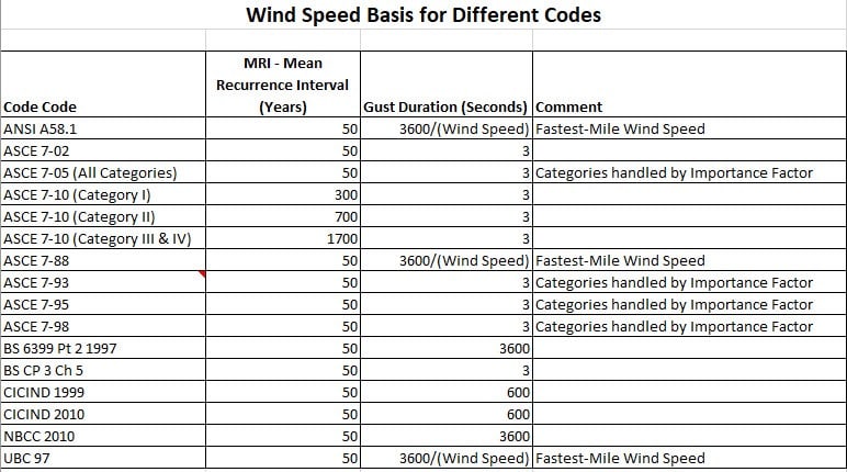
Wind load equations per ASCE 7-05 or earlier takes the Basic Wind Speed and calculates the wind pressure based on this speed. The Basic Wind Speed per ASCE 7-05 and earlier editions is based on 3-sec. gust at 33 feet elevation, Exposure C, and 50 year MRI. However, note that ASCE 7-88 and earlier, the Basic Wind Speed was not the 3 sec gust at 33 feet elevation, but the Fastest Mile Wind Speed (fastest average speed based on a particle in the wind as it travels 1 mile downstream) at 50 year MRI. There is only one map for Basic Wind Speed in ASCE 7-05 and earlier editions. Different Risk Categories I, II, III, IV were handled by multiplying the calculated wind pressure by an importance factor for each Risk Category. For Allowable/Working Stress calculations the resulting wind pressure calculated by ASCE 7-05 is multiplied by a load factor of 1.0 and for LFRD calculations the factor is 1.6.

Wind_Load_Chart_msusqp.jpg


ASCE 7-10 changed the Basic Wind Speed calculations to include the importance factor and LFRD load factor directly into the Basic Wind Speed maps, and developed different maps for different Risk Categories/Importance Factors which resulted in multiple windspeed maps based on Risk Category and MRI. In effect this made the wind speed charts of ASCE 7-10 about 1.6 times the values of wind speed the ASCE 7-05 (and earlier) maps. Therefore, the ASCE 7-10 charts which included the 1.6 load factor and importance factor in them are not a measure of true 50 year MRI wind speed. To get back to the true Basic Wind Speed per ASCE 7-05 and earlier (a true wind speed based on 50 year MRI, 3-sec gust, Exposure C) it is needed to multiply the resulting wind pressure “qz” by 0.6 or velocity by 0.78, since multiplying directly times the velocity (0.78V)2 is same as multiplying the resulting velocity squared 0.6(V2) the velocity pressure term, and 1.6 x .6 is approximately 1.0 which gets you back to ASCE 7-05 values for wind that does not include the importance factor and LFRD load factor. This is because mechanical calculations are traditionally based on the allowable/working stress design which are based on the true 50 year MRI wind, 3-sec gust, 33 feet level, Exposure C.
 
Part 2

API 650- 2000

API 650 (2000) requirements for overturning resistance as below in Bold. Note this is the only reference to wind loading in API 650 (2000). There is no indication of wind loading requirements for design loads in “Design Considerations” section, as it is left up to the designer to determine external loading such as wind.

3.1 1.1 When specified by the purchaser, overturning stability shall be calculated using the following procedure:
The wind load or pressure shall be assumed to be 1.4 kPa (30 lbf/ft2) on vertical plane surfaces, 0.86 kPa (18 lbf/ft2) on projected area as of cylindrical surfaces, and 0.72 kPa (15 lbflft2) on projected areas of conical and double-curved surfaces.

These wind pressures are based on a wind velocity 160k m/h (100 mph). For structures designed for wind velocities other than 160 km/h (100 mph), the wind loads specified above shall be adjusted in proportion to the following ratio:

In SI units:
(V/160)[sup]2[/sup]
where
V = wind velocity, in km/h, as specified by the purchaser.

In US Customary units:
(V/100)[sup]2[/sup]
V = wind velocity, in mph, as specified by the purchaser.


So basically older API 650 versions used a wind speed of 100 miles per hour as a basis for calculating the theoretical wind load. My understanding is this wind speed is not the Basic Wind Speed per 3 sec gust but is the Fastest Mile Wind Speed by the wording used in the Code excerpt above. This results in the following:

P = 0.00256 V2/2g = 25.6 lb/ft2 then multiplied by other factors to get 30 lb/ft2 for a flat surface.

No mention is made in API 650 what additional factors are used get from the theoretical wind pressure of 25.6 lb/ft2 to 30 lb/ft2. Now for a curved surface such as a tank with a Shape Factor Cf of 0.6 then the load on the curved surface would be:

P = 0.6(30) = 18 lb/ft2

This is how for a curved surface in API 650 (2000) the based value is 18 lb/ft2– by using a shape factor of 0.6 for a cylindrical surface.
 
Part 3

API 650-2013

API 650 – 2013 added complete new requirements for determining wind load in Section 5.2.1 (k) for the purpose of being consistent and adjusting for the revised wind maps of ASCE 7-10 which included the importance factor and LFRD load factor directly in the wind maps. The new section is as follows:

5.2.1k) Wind (W): The design wind speed (V) shall be either:

— the 3-sec gust design wind speed determined from ASCE 7-05 multiplied by √I, Figure 6-1; or
— the 3-sec gust design wind speed determined from ASCE 7-10 for risk category specified by the Purchaser (Figure 26.5-1 A, Figure 26.5-1B, or Figure 26.5-1C) multiplied by 0.78; or
— the 3-sec gust design wind speed specified by the Purchaser, which shall be for a 3-sec gust based on a 2 % annual probability of being exceeded [50-year mean recurrence interval]. The 3-sec gust wind speed used shall be reported to the Purchaser.

1) Design wind pressure (PWS and PWR) using design wind speed (V): The design wind pressure on shell (PWS) shall be 0.86 kPa (V/190)[sup]2[/sup], ([18 lbf/ft2][V/120][sup]2[/sup]) on vertical projected areas of cylindrical surfaces. The design wind uplift pressure on roof (PWR) shall be 1.44 kPa (V/190)[sup]2[/sup], ([30 lbf/ft2][V/120][sup]2[/sup]) (see item 2) on horizontal projected areas of conical or doubly curved surfaces. These design wind pressures are in accordance with ASCE 7-05 for wind exposure Category C. As alternatives, pressures may be determined in accordance with:

a) ASCE 7-05 (exposure category and importance factor provided by Purchaser); or
b) ASCE 7-10 (exposure category and risk category provided by Purchaser) with either velocity multiplied by 0.78 or the ASCE 7-10 pressure multiplied by 0.6; or
c) a national standard for the specific conditions for the tank being designed.

2) The design uplift pressure on the roof (wind plus internal pressure) need not exceed 1.6 times the design pressure P determined in F.4.1.

3) Windward and leeward horizontal wind loads on the roof are conservatively equal and opposite and therefore they are not included in the above pressures.

4) Fastest mile wind speed times 1.2 is approximately equal to 3-sec gust wind speed (V).


NOTE ASCE 7-10 wind velocities now have LRFD load factors and risk category (importance factors) built in, whereas API 650 uses the working stress. The 0.78 factor applied to the ASCE 7-10 wind speed provides a conversion to working stress levels.

So to compensate for the fact that the LFRD load factor and importance factors are now included in the wind maps of ASCE 7-10, and to get back to the actual real 50 year MRI Basic Wind Speed values of ASCE 7 wind maps prior to ASCE 7-10, the Basic Wind Speeds of ASCE 7-10 wind maps are modified to multiply the 0.6 factor based on calculated wind pressure and 0.78 applied to wind velocity. Since now there are multiple wind maps in ASCE 7-10 and above based on Risk Category, the above part b) allows for the Purchaser to choose which Risk Category map to use depending on how conservative the Purchaser desires the design to be. Therefore, it is my understanding that you cannot choose any other MRI and conversion other than per ASCE 7-10 maps and can only use factors 0.6/0.78 to convert to ASCE-05, 50 year MRI maps.
 
Part 4 of 4

For the ASCE 7-05 conversion indicated in API 650 (2013) above in paragraph k) first sentence, since the load factors and importance factors are not included to begin with in ASCE 7-05 wind maps, then the ASCE 7-05 maps are the true 50 MRI, 3-sec gust, 33 feet level, Exposure C values. Therefore, they do not need to be converted back using the 0.6 and 0.78 factors. However, conversion of the ASCE 7-05 maps require multiplying by the SQRT “I” (importance factor) as indicated. This is because the older API 650 standards, which the later API 650 standards are still based on, never did include an importance factor but based the wind speed on the Fastest Mile Wind Speed of 100 mph as previously indicated, which resulted in 30 lb/ft2 for flat surfaces and 18 lb/ft2 for cylindrical surfaces as previously indicated. The later versions of API 650 now are now coordinated to be consistent with the later ASCE 7’s as indicated in the API 650 (2013) excerpt above to use the 3-sec gust wind speed and importance factor as follows:

1) Use the wind basis as the 3-sec gust wind speed instead of the Fastest Mile Wind Speed. The 3-sec gust wind speed is approximately 1.2 times the Fastest Mile Wind Speed per API 650 (2013) part 4) above. Therefore, the new 3-gust wind speed basis, based on the 100 mph fastest mile speed of the older API 650 editions is now 1.2*100 = 120 mph. Keeping the basic design wind pressure per older API 650 versions at 30/18 lb/ft2 but normalizing these values based on the 3-sec gust speed, instead of Fastest Mile Speed, then the 30/18 lb/ft2 is multiplied by the 3-sec. gust value “V” per API 650 (2013) paragraph k) above using equation (V/120)2 as indicated in paragraph 1) above. By doing this the 30/18 lb/ft2 basis, based on fastest mile wind speed, has been adjusted based on 3-sec. gust wind speed “V” normalized to 120 mph 3-sec gust value.

2) Include an importance factor which the older API 650 did not include. To be consistent with the later ASCE 7 editions which use a 3-gust wind speed V with and importance factor also included, the basis wind pressure of 30/18 lb/ft2 also must be adjusted for importance factor before it is inserted into the equation (V/120)2. Simplified without showing the other factors this results in the ASCE 7 equation wind pressure is proportional to I(V2) or (IV)2 or SQRT(I)(V2). Therefore, to include the importance factor to the 3-sec. gust wind speed of the API 7-05 maps per k) above, multiplication by SQRT(I) is required. Note that for conversion of the ASCE 7-10 to ASCE 7-05 calculation the importance factor multiplication is not required since the API 7-10 maps already include the importance factors.


Snickster said:
ASCE 7-10 changed the Basic Wind Speed calculations to include the importance factor and LFRD load factor directly into the Basic Wind Speed maps, and developed different maps for different Risk Categories/Importance Factors which resulted in multiple windspeed maps based on Risk Category and MRI. In effect this made the wind speed charts of ASCE 7-10 about 1.6 times the values of wind speed the ASCE 7-05 (and earlier) maps. Therefore, the ASCE 7-10 charts which included the 1.6 load factor and importance factor in them are not a measure of true 50 year MRI wind speed. To get back to the true Basic Wind Speed per ASCE 7-05 and earlier (a true wind speed based on 50 year MRI, 3-sec gust, Exposure C) it is needed to multiply the resulting wind pressure “qz” by 0.6 or velocity by 0.78, since multiplying directly times the velocity (0.78V)2 is same as multiplying the resulting velocity squared 0.6(V2) the velocity pressure term, and 1.6 x .6 is approximately 1.0 which gets you back to ASCE 7-05 values for wind that does not include the importance factor and LFRD load factor. This is because mechanical calculations are traditionally based on the allowable/working stress design which are based on the true 50 year MRI wind, 3-sec gust, 33 feet level, Exposure C.
Does mechanical allowable stress method exclude importance factor?
 
If now strength wind speed V[sub]1700[/sub] is provided, how should we calculate wind load as per API 650?
I think that only formula provided in Page 509, ASCE 7-10, is effective.
V[sub]1700[/sub]/V[sub]50[/sub]=[0.36+0.1ln(12*1700)]
So as per Chapter 5.2, API 650, load combinations, we can use V[sub]50[/sub], considering importance factor, but this V[sub]50[/sub] is not V[sub]1700[/sub]/1.6.
Or we can use V[sub]1700[/sub], without considering importance factor.
 
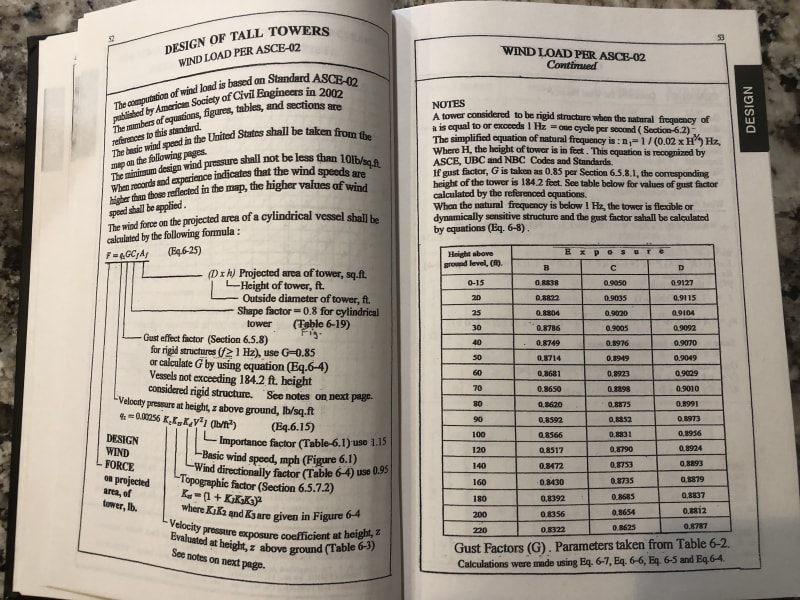
Yes but a the importance factor, and other factors, is applied after the theoretical wind pressure 0.00256V[sup]2[/sup]/2g is calculated. Here is a typical older calculation based on before ASCE 7-10 for a pressure vessel (same for piping).

I remember now that somewhere along the way ASCE started including the shape factor in their basic wind loads when the LFRD method was introduced. Mechanical standards adjusted for this. I don't remember the specifics but somehow the different mechanical standards accounted for this in different ways. It was very confusing really to deal with. Programs such as Caesar still used the old method of having the shape factor multiplied by the theoretical velocity pressure.

Here is a pressure vessel calculation (from Pressure Vessel Handbook, Eugene Megyesy, 13th edition 2004), using 0.8 as shape factor - piping uses same equations but uses a shape factor of 0.5 to 0.7, but 0.6 typically. Note that the importance factor "I" is multiplied by the wind pressure not velocity - to multiply by velocity, need to use SQRT "I" times "V" instead as shown in API 650 (2013)

IMG_2146_kntjpv.jpg
 
If now strength wind speed V1700 is provided, how should we calculate wind load as per API 650?

I think that only formula provided in Page 509, ASCE 7-10, is effective.
V1700/V50=[0.36+0.1ln(12*1700)]

So as per Chapter 5.2, API 650, load combinations, we can use V50, considering importance factor, but this V50 is not V1700/1.6.

Or we can use V1700, without considering importance factor.


My understanding, but I may be wrong, is that the conversion from V1700 to V50 shown in ASCE 7-10 and based on the ASCE 7-10 wind maps as you show above, will still include the LFRD load factor and importance factor in the converted value so it is not the true 50 year MRI to use in a mechanical calculation such as API 650. To get the true 50 year MRI used in a mechanical calculation based on the allowable/working stress design, that does not have the LFRD Load factor and importance factor included, you need to make the conversion per API 650 - 0.6 times wind pressure or 0.78 times velocity (which results in same adjustment). This will take out the load factor and importance factor from the ASCE 7-10 MRI speed. The conversion you show above only converts one ASCE 7-10 MRI wind speed to another and both have the LFRD and importance factor still included in them.

Also it is my understanding that per API 650 you have the option of using the 300, 700 or 1400 wind speed maps values depending on how conservative you want to be based on your own engineering judgement for the location involved.


I see that there is some confusion now in API 650 conversion requirements. Do you convert to V50 MRI using ASCE 7-10 equation then multiply by 0.6/0.78? or do you take the values straight from the V300, 700 or 1400 wind maps and multiply by 0.6/0.78.

There are three possibilities per API 650:

5.2.1k) Wind (W): The design wind speed (V) shall be either:

— the 3-sec gust design wind speed determined from ASCE 7-05 multiplied by √I, Figure 6-1; or
— the 3-sec gust design wind speed determined from ASCE 7-10 for risk category specified by the Purchaser (Figure 26.5-1 A, Figure 26.5-1B, or Figure 26.5-1C) multiplied by 0.78; or
— the 3-sec gust design wind speed specified by the Purchaser, which shall be for a 3-sec gust based on a 2 % annual probability of being exceeded [50-year mean recurrence interval]. The 3-sec gust wind speed used shall be reported to the Purchaser.


The first option is for converting from ASCE 7-05 wind maps in which you just multiply by SQRT "I".

The second option is if you use the ASCE 7-10 wind maps for 300, 700 or 1400 MRI which I believe you must multiply by 0.6 (x wind pressure) or 0.78 (x velocity) which I spoke of in my previous post. Note that this will take out the added LRFD load factor of 1.6 but it will keep the importance factor since each Risk Category Map I, II, III, IV increased wind speed values are due to importance factor. So the importance factored value of wind speed is maintained even after multiplying by 0.6/0.78. What MRI maps you use is based on engineering judgement for the location involved.

The third option is a little tricky in what it is saying. I believe it is saying you can just determine your own 50 year MRI based on historical wind data collected for the location involved without any other factor 0.6/0.78 applied. If you really want, although it will be very conservative, you could even use the converted V50 value per the ASCE 7-10 calculation you previously posted (without any additional conversion factors 0.6/0.78 applied) as it will surely be greater than the actual V50 MRI for any given area I assume being that the 1.6 LFRD factor will still be included.


Snickster said:
My understanding, but I may be wrong, is that the conversion from V1700 to V50 shown in ASCE 7-10 and based on the ASCE 7-10 wind maps as you show above, will still include the LFRD load factor and importance factor in the converted value so it is not the true 50 year MRI to use in a mechanical calculation such as API 650. To get the true 50 year MRI used in a mechanical calculation based on the allowable/working stress design, that does not have the LFRD Load factor and importance factor included, you need to make the conversion per API 650 - 0.6 times wind pressure or 0.78 times velocity (which results in same adjustment). This will take out the load factor and importance factor from the ASCE 7-10 MRI speed. The conversion you show above only converts one ASCE 7-10 MRI wind speed to another and both have the LFRD and importance factor still included in them.

Also it is my understanding that per API 650 you have the option of using the 300, 700 or 1400 wind speed maps values depending on how conservative you want to be based on your own engineering judgement for the location involved.
The question is that our project are not in the USA. We don't have any wind speed maps.
 
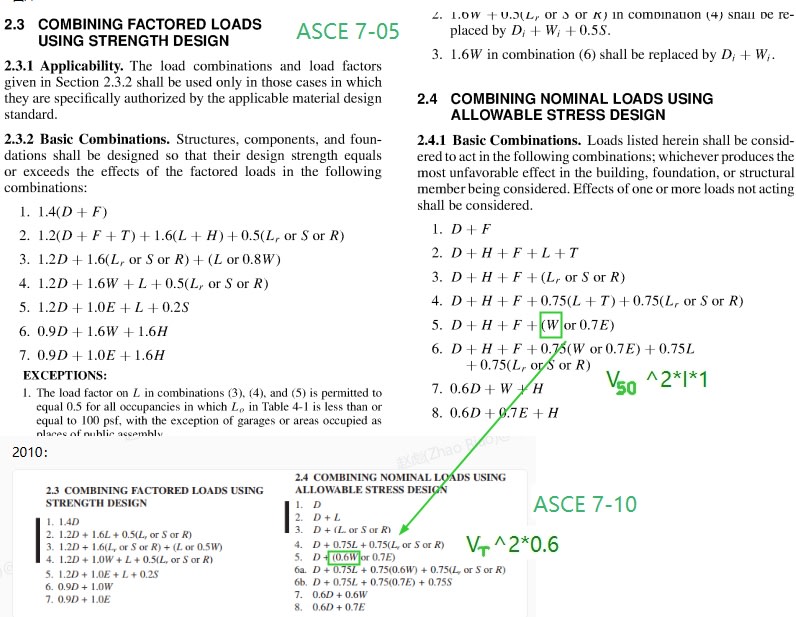
CatchBE8E_10-18-_10-22-13-40-09_itc30w.jpg
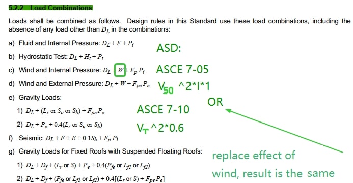
Catch59BE_10-18-_10-22-13-40-09_colqji.jpg

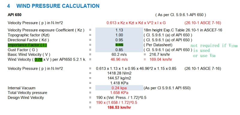
As shown in ASCE 7-05 & 7-10, take load combinations for stress for example. "W" in ASCE 7-05 and "0.6W" in ASCE 7-10 is of the same effect.
If now we have V[sub]1700[/sub] calibrated based on strength limit state and ASCE 7-10, the load effect is:
P=0.613K[sub]Z[/sub]K[sub]ZT[/sub]K[sub]D[/sub]V[sup]2[/sup]*0.6
Or as per ASCE 7-05:
P=0.613K[sub]Z[/sub]K[sub]ZT[/sub]K[sub]D[/sub]V[sub]50[/sub][sup]2[/sup]*I*1.0.
V[sub]50[/sub] is obtained as per formula given in Page 509, ASCE 7-10.

There is a wrong example: risk category III
Our mechanical engineer use V[sub]1700[/sub], divided by 0.78, (they think that V[sub]1700[/sub]/0.78=V[sub]50[/sub], and they think V[sub]T[/sub]/0.78=V[sub]50[/sub])
Then they use "V50" and consider importance factor 1.15 for risk category III.
Catch65C6_10-18-_10-22-13-53-47_iyvyvy.jpg

This is also my understanding.
 
There must be some wind speed maps somewhere. There must be building codes for your area that specifies wind speed for structural engineers to design buildings. I would ask a structural engineer for wind speed maps for 50 year MRI wind, 3-sec gust, Exposure C, and use those values without adjustment except for elevation if necessary.
 
I just saw your new post after I posted my last response. I will look at it tomorrow, it is getting late here.
 
Snickster said:
There must be some wind speed maps somewhere. There must be building codes for your area that specifies wind speed for structural engineers to design buildings. I would ask a structural engineer for wind speed maps for 50 year MRI wind, 3-sec gust, Exposure C, and use those values without adjustment except for elevation if necessary.
Is team meeting or zoom meeting allowed in our forum?
 
There is a wrong example: risk category III
Our mechanical engineer use V1700, divided by 0.78, (they think that V1700/0.78=V50, and they think VT/0.78=V50)
Then they use "V50" and consider importance factor 1.15 for risk category III.

I am not that familiar with the ASCE 7 code and all the load combination you listed in your post above. However, the equation listed on your latest post above noted as 26. 10-1 ASCE 7-16 is the basic equation I am familiar with for use in calculation of wind load on mechanical equipment. My understanding that "V" in this equation is the 3-sec gust 50-year MRI wind speed without LFRD load factor or Importance Factor "I" included.

Therefore it is my understanding that to obtain "V" to use in this equation from wind speed maps for V[sub]1700[/sub] Risk Category III of ASCE 7-16 you would adjust as follow:

Multiply V[sub]1700[/sub] of Figure 26.5-1B by 0.78 to remove the LFRD load factor. The resulting "V" is now, as I understand, the V[sub]1700[/sub] wind speed which corresponds to the 50 year MRI wind speed but with importance factor of Category III based on ASCE 7-05 editions still included.

Therefore for use in the equation indicated above you would not need to multiply by "I" since "I" is still included in the converted velocity. Multiplying velocity by 0.78 only removes the LFRD load factor added to ASCE 7-05 wind maps to obtain ASCE 7-10 and above wind maps but does not remove the Importance Factor, which was also added to ASCE 7-05 wind maps to obtain ASCE 7-10 and above wind maps.

It looks like the equation you list above for wind pressure was based on ASCE 7-05 and earlier when wind maps did not include the importance factor so you had to then multiply the resulting wind pressure by "I" or multiply the velocity by SQRT "I" which is same thing. This shown in the first option of API 5.2.1(k):

5.2.1k) Wind (W): The design wind speed (V) shall be either:

— the 3-sec gust design wind speed determined from ASCE 7-05 multiplied by √I, Figure 6-1


Part and Inventory Search

Sponsor