Eng-Tips is the largest engineering community on the Internet

Intelligent Work Forums for Engineering Professionals

Fastener Analysis in Built Up Beam

willindsey

Aerospace
Apr 18, 2023
7
0
0
US
Hello,

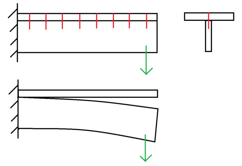
I am working out a problem at work. To frame the problem as a conceptual one, I am designing a bolted connection to secure a flange to a web. The bolts are installed through the "top" of the flange and into the web. Say its a cantilever beam with a point load at the tip. I have computed the shear flow and determined the shear stress in the fasteners. Is there also a tensile/compressive load through the fasteners? If so, how would one go about finding that load?

It seems in the real world that it is unlikely the fasteners are in pure shear and there would be some form of a tensile/shear loading on the fasteners. An idea I am considering to compute the tensile/compressive fastener loading is to figure out the forces required for each component to have the same deflection of the built up beam. The max force would then dictate the tensile/compressive force in the fastener. This would essentially account for load sharing and continuity.

Any references and resources would be much appreciated.

Thank you all
 
Replies continue below

Recommended for you

willindsey said:
An idea I am considering to compute the tensile/compressive fastener loading is to figure out the forces required for each component to have the same deflection of the built up beam.

That's about it actually. You've got good instincts. For most practical applications, the tension / compression in the fasteners can be neglected.

Since you've asked about the nuance, here's how it works.

1) Your composite behavior is kind of the sum of two kinds of behavior:

a) The whole section action compositely.

b) Each individual part trying to be a beam in it's own right. Shallow trusses with stiff chords do this noticeably.

2) Because of [1b], it is possible that any part may be somewhat:

a) bearing upon its neighbor pieces or;

b) pulling away from its neighbor pieces.

3) In real world applications, whether there is compression / tension at the interfaces is also a function of where the loads are applied vertically on the cross section. Does the load need to get shifted up/down to the piece being considered? Or shifted away from the piece being considered?

4) Most composite sections will have will have flanges that are so flexible relative to the composite section that any tension / compression that would be induced can be safely ignored.

5) Obviously, localized load delivery to connected parts can create localized connection demand between those parts.
 
why ould the fasteners not be in pure shear ? Say your beam had two caps (or chords) ... say Tee (or angle) extrusions and a web and they are joined together by a row of fasteners between the web and the "standing" leg (one row for the upper cap, one for the lower). Why wouldn't these be in shear ??

Now if you have fasteners in the cap ... say your web has flanges (like a C-section) and your caps are a strap. Now I think there is a small tension load in the fasteners (to make the straps bend). Something like the transverse shear on the strap portion of the section (a la VQ/I)

"Wir hoffen, dass dieses Mal alles gut gehen wird!"
General Paulus, Nov 1942, outside Stalingrad after the launch of Operation Uranus.
 
KootK summed up exactly what I was thinking.

Assuming it is a T-section, if the loading is on the web, then there would be a tension component transferred to the flange so that the two pieces deflect the same amount. If the shear connectors did not have any capacity to carry tension, then the web and flange would just separate. If the loading was on the flange instead, then I think you would only need the shear capacity in the connectors.

Agree with OP and KootK that the tension required in the shear connectors is just that required to cause the flange to deflect the same amount as the web (probably very little as KootK said).

Screenshot_2024-10-17_142613_ydstpd.png
 
While we are talking built up beams, as a tangent question...

I recently was involved in a project this built up beam (shown below) it used bolts for transferring shear between the beams and welds for transferring the shear flow. Bolts are not assumed to carry shear flow but are still within capacity to do so, shear flow is assumed to be carried by the welds. Does anybody see any potential issues or problems with this design? Assuming the bolts and welds are designed suitable for the loads. The reasons for the used of the built up beam vs a simple I beam are convoluted.

temp_pjxujk.png
 
Thank you all for your input this has been very helpful.

@SWComposites this is an aerospace application and the diagram is essentially what bugbus illustrated.

Thank you
 
Ok, sorry to be blunt, but that is a horrible design. Tapping screws into a web is not appropriate for manufacturing or structurally. Bolted joints should be designed so the fasteners are in shear. Yes, in some cases fasteners are in tension, but those are thru bolts with heads / nuts to react the tension; the applied tensile load should not be in a tapped hole.

You should repost this in the aircraft engineering forum with a sketch; most people here are civil structures engineers.

 
human909 said:
Does anybody see any potential issues or problems with this design?

I like it. I assume that the intention is to shield the welds from the tension demand and I feel that the flexibility of the flange, and the pre-tensioning in the bolts, plausibly accomplish that without the usual load sharing issues negatively affecting the weld.

When reinforcing is cut short of the supports, there will be both a concentrated shear demand and a concentrated tension demand at the cut off. Usually one sees a long bit of weld at the ends for this reason. In this case, perhaps a group of two or three bolt for similar reasons.

That said:

1) Maybe you've covered this in other details and/or;

2) Maybe the demand is so small that concentrated connection at the end is unnecessary. It is true that, the closer to the member end the cutoff is located, the lower the demand for concentrated connection will be.

I'm considering this a static load application. If it's dynamic / fatigue, I'd have to noodle on it some more.
 
SWComposites said:
Ok, sorry to be blunt, but that is a horrible design. Tapping screws into a web is not appropriate for manufacturing or structurally. Bolted joints should be designed so the fasteners are in shear. Yes, in some cases fasteners are in tension, but those are thru bolts with heads / nuts to react the tension; the applied tensile load should not be in a tapped hole.

You should repost this in the aircraft engineering forum with a sketch; most people here are civil structures engineers.

The example discussed is conceptual and is framed as an academic problem to better understand the analysis approach for computing the tension in the fasteners for this particular scenario. It is intended to be agnostic of the end application. For this problem, are you able to provide additional input on how to go about computing the tensile load within the fasteners for this built-up beam? Computing the actual tensile load in the fasteners would be helpful to understand your point of view. Thank you.
 
Compute the vertical tensile stress in the top of the web, either by hand or with a simple shell element FEA. That tensile load is transferred to the flange via the fasteners; just convert from stress to point loads at each fastener.
 
sure we can give you answers, but I think you learn more in figuring out things on your own. Show us your work if you want a 2nd opinion, or if your results looks "silly".

you have a sketch of the beam ... how does the cap strip deflect (as it does deflect to match the beam/web it is attached to) ? by "how" I mean what force is causing it to deflect, and once you say "force" you're into free body diagrams. Once you look at "traditional" analysis approaches (the web resists the shear) you'll see there is "nothing" driving the cap strip to deflect ... so how to modify the traditional analysis approach to make it "right".

Maybe part of this thought process is imagine how the beam works if it were one piece.

"Wir hoffen, dass dieses Mal alles gut gehen wird!"
General Paulus, Nov 1942, outside Stalingrad after the launch of Operation Uranus.
 
SWComposites said:
why would you add bolts in addition to the welds? the bolts won't pick up load until the welds fail.
The bolts won't pick up shear flow but they will transfer any vertical load as pointed out by Kootk. (Well that is the intent.)

KootK said:
I like it. I assume that the intention is to shield the welds from the tension demand and I feel that the flexibility of the flange, and the pre-tensioning in the bolts, plausibly accomplish that without the usual load sharing issues negatively affecting the weld.
Exactly that is the intention. I believe it accomplishes that but I welcome alternative thoughts. Pre tensioned bolts should be stiffer in the vertical direction than the welded flange edges. I'd be somewhat concerned on the welded flanges without bolts due to prying effects. Especially with staggered welds.

KootK said:
When reinforcing is cut short of the supports, there will be both a concentrated shear demand and a concentrated tension demand at the cut off. Usually one sees a long bit of weld at the ends for this reason. In this case, perhaps a group of two or three bolt for similar reasons.
Agreed. There are more bolts clustered at the end rather than the middle, and they were suitably and conservatively sized. The tension demand isn't super high because the web depth is significantly smaller in the second beam than the first.

KootK said:
That said:

1) Maybe you've covered this in other details and/or; Yes it has been covered by suitable calculations.

2) Maybe the demand is so small that concentrated connection at the end is unnecessary. It is true that, the closer to the member end the cutoff is located, the lower the demand for concentrated connection will be. The demand is high as they are 'big beams' but the demand on the bolts isn't super high as it is proportional to two web sizes most of the beam shear ~70% is in the top web which is deeper and thicker.

I'm considering this a static load application. If it's dynamic / fatigue, I'd have to noodle on it some more. Essentially a static load. It supports a bulk material storage so the load will change significantly depending on bulk material stored by not in a rapid fashion.


Thanks for you feedback. The design is a little different from what is normally seen but I believe it is effective. I certainly hope it is given the significant loads it will carry! I welcome any further comments by others either positive or negative.

(PS. I didn't state it initially but it was almost implied. The design was mine. I thought it was a clever solution to challenge a client was facing. A few factors have caused me to second guess myself.

In addition to hand calculation I also ran an an FEA with the connections and welds models and the weld and bolt interactions were as expected. I also got nice pretty colour that really show the load flow at the transition. I'll see if I can dig it up.)
 
Back
Top