Continue to Site

Eng-Tips is the largest engineering community on the Internet

Intelligent Work Forums for Engineering Professionals

  • Congratulations cowski on being selected by the Eng-Tips community for having the most helpful posts in the forums last week. Way to Go!

Determining flow through a half full gravity return oil line

Henrique Orlandini

Mechanical
Dec 11, 2017
19
Hello again. I'm working on a spreadsheet to aid my coworkers in sizing a Lube Oil System as per API 614 6th editions, and one of the requirements is that all gravity return oil lines must be at most half full.

So, what I've been trying to do is to determine what is the flow that could run through an exactly half full pipe. I tried looking first into Manning's formula first, but it doesn't sit well with lubricating oil due to the vastly different viscosities of water and oil. Then I tried to look into Darcy-Weisbach formula, but I couldn't also get a solution because the friction factor for laminar flow depends on the Reynolds number and the Reynolds number depends on the flow, which is what I'm trying to determine. Going into iterative or analytical solutions isn't feasible either because I need to put this on an Excel spreadsheet.

Basically, I need some light on those scenarios:
  • Scenario 1: the pipe dimensions are known; it's a gravity return oil line (no pressure other than ATM) and the wetted area is set to 50% (half full pipe). Is there a way to determine the flow through that area?
  • Scenario 2: the pipe dimensions are known; it's a gravity return oil line (no pressure other than ATM) and the flowrate is also known. Is there a way to determine the wetted area?
Any help would be greatly appreciated, thanks in advance!
 
Replies continue below

Recommended for you

Are we talking sloped pipe here or vertical returns.

As you're aware, temperature will play a huge role in viscosity and flow rates.

what sort of viscosities are we talking about here?

How accurate do you need to be.

Assume something like 0.1m/sec? that gives you flow. You are going ot be jumping some big differences with pipe sizes at 1 to 4" maybe.

This is lube oil. You can't be talking vast amounts so is it a 2" or 2 1/2 " pipe isn't really going to kill anything.

I think you're in danger of trying to work something out far more accurately than you actually need when the parameters can change hugely between each application for different oil, different temperatures, different slopes.
Sorry, I should've given more details. I usually work with lubricating oil with temperatures ranging from 40 - 60 °C, so their viscosities should be around 21 - 46 cSt. For a commercial efficient sizing, we usually try to get a flow speed between 0.7 and 1.8 m/s. The slope will range from 40 mm/m (minimum for API 614) plus whatever pitch/roll from the ship.

And I'll be honest, when I started reading the different approaches to partially full pipe calculations, especially with fluids other than water, I thought to myself that I was overengineering (again). I'm leaning into just following the OEM connections sizes and keep an eye out for anything out of the ordinary.
 
Here is a simple approximation that you could use as a sanity check. It would err on the conservative side so you may slightly oversize your pipes, but it would be a good check on the feasibility of the design.

You said that you looked into the Darcy-Weisbach formula but you don't want to have to resort to an iterative solution. But in viscous or laminar flow the friction factor is a simple relation of the Reynolds number (f = 64/Re) and this allows the math to be simplified to achieve an explicit solution. See the Hagen-Poiseuille equation.

Although Darcy-Weisbach applies to full flow in round pipes you could try two different approaches. Try using the hydraulic radius rather than the true pipe diameter, or try modeling your pipe as a smaller pipe with the same cross section as half the cross section of the true pipe size.

This approach is unlikely to give a very accurate result, but because you really have a very limited range of possible pipe sizes and in fact you are faced with a size selection decision rather than a design, the pipe that is eventually selected is likely to be oversized anyway.
 
Last edited:
Avoid high or low point piping pockets in the return lines to the main oil tank - all return lines should be free venting so entrained air or process gas doesnt get trapped at these pockets. Hydraulic flow equations wont help if these lines are pocketed.
 

The paper I cited was authored by P. K. Swamee, who formulated the famous Swamee-Jain friction factor formula.

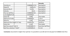
I have done a preliminary calculation based on your data and above reference as below:
1744345992078.png
Disclaimer: Please check with your own past experience and reference above before using the same.
 
Sorry, I should've given more details. I usually work with lubricating oil with temperatures ranging from 40 - 60 °C, so their viscosities should be around 21 - 46 cSt. For a commercial efficient sizing, we usually try to get a flow speed between 0.7 and 1.8 m/s. The slope will range from 40 mm/m (minimum for API 614) plus whatever pitch/roll from the ship.

And I'll be honest, when I started reading the different approaches to partially full pipe calculations, especially with fluids other than water, I thought to myself that I was overengineering (again). I'm leaning into just following the OEM connections sizes and keep an eye out for anything out of the ordinary.
I'd just be tempted to do some testing using say 3m of pipe at different slopes with a short section of transparent pipe so you can judge when you get to half full.

Laminar half full open channel flow isn't the easiest thing to calculate reliably and ultimately how close do you want to get to ideal? Get it a bit wrong and fill the pipe design you get slugging and possible loss or spilling of lubricating oil. Is it worth it?
 
Self venting gravity flow lines are typically sized to keep the Froude number N_Fr < 0.31 (in SI units). See equation 6-138 in Perry Chem Engg Handbook (7th edn) for N_Fr expression which accounts for liquids with density other than water - there is no viscosity term here though, so maybe keep N_Fr < 0.31x0.5 say for lube oil.
 
Last edited:
Hello again. I'm working on a spreadsheet to aid my coworkers in sizing a Lube Oil System as per API 614 6th editions, and one of the requirements is that all gravity return oil lines must be at most half full.

So, what I've been trying to do is to determine what is the flow that could run through an exactly half full pipe. I tried looking first into Manning's formula first, but it doesn't sit well with lubricating oil due to the vastly different viscosities of water and oil. Then I tried to look into Darcy-Weisbach formula, but I couldn't also get a solution because the friction factor for laminar flow depends on the Reynolds number and the Reynolds number depends on the flow, which is what I'm trying to determine. Going into iterative or analytical solutions isn't feasible either because I need to put this on an Excel spreadsheet.

Basically, I need some light on those scenarios:
  • Scenario 1: the pipe dimensions are known; it's a gravity return oil line (no pressure other than ATM) and the wetted area is set to 50% (half full pipe). Is there a way to determine the flow through that area?
  • Scenario 2: the pipe dimensions are known; it's a gravity return oil line (no pressure other than ATM) and the flowrate is also known. Is there a way to determine the wetted area?
Any help would be greatly appreciated, thanks in advance!
1. For gravity drain, the pipe size and the flow rates are matched to the available energy. The available energy is the elevation difference (termed head) between the supply and delivery points.
For maximum natural flow, the available energy equals the friction loss in the pipe.
You can choose a required flow rate, assume oil velocity (typical 1.5 m/s), then determine the pipe size (d).
From your layout, you will have the tank elevations, and determine the total pipe length for the given slope.
Determine the total friction loss (including pipes, fittings, valves etc) using hagen-poiseuille equation that factors in the viscosity.
All the energy in the elevation head will be used:
• to provide the ‘end-of-pipe’ pressure requirement (in your case zero, open to atm).
• the rest will be used up as friction to provide the given flow through the pipe.

You will need to iterate if it doesn't match. Technically, you will not get flow if friction loss exceeds the available head.

2. What is half-full pipe criteria?
With half-full pipe flow rate, the friction loss will be reduced, which means the available energy can be reduced, which further means the top tank liquid level can be reduced. In other words, this will give the low level set-point for the top tank.
 
@goutam_freelance Thanks, I'll look into to see if I can use it on my spreadsheet.

@LittleInch I'll be honest, you wouldn't be the first one to tell me this. It's been on my to-do list to charm some people so we can make a pseudo-prototype arrangement to get out of theory territory and get some actual evidence on how things work.

@georgeverghese I didn't even think into looking into Chem Eng resources, but it makes sense in hindsight.

I appreciate all the answers, I was used to working with pressurized pipes and I was basing myself on other people's know-how when working with gravity flow lines, but this seems like it's another beast. I'll get there eventually. Thanks y'all.
 

Part and Inventory Search

Sponsor