Continue to Site

Eng-Tips is the largest engineering community on the Internet

Intelligent Work Forums for Engineering Professionals

  • Congratulations SDETERS on being selected by the Eng-Tips community for having the most helpful posts in the forums last week. Way to Go!

Confusions on drawing 1

dulman123

Mechanical
Dec 22, 2024
14
Hello!
I've posted this in a wrong group.
Now I'm reposting it here wondering professional answers and suggestions from this group.
Thank you in advance!
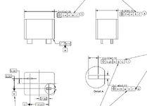
I got confused if the drawing attached is correct or not, actually the 1st drawing was from my customer and probably their drawing follow ISO standard.
The other 2 proposed drawing are based on my understanding and I think they are clearer and more reasonable.
However I'm a new user of GD&T and I have no confidence of it.

Design intent:
This part is an electronic component with a plastic block and two flat pins(two tabs) protruding the block.
It will be mounted on a PCB with the two pins soldered in PCB holes(slotted hole)
While the pins are in the PCB holes, the upper block are supposed to stay vertical and not shift too much with respect to the pins.
Because if they shift much, the component will take up more room on the PCB and may interfere with adjacent components.

So the design intent is to maintain a good interrelated position among the two pins(taken as a group)
That's why I specify positional tolerance for the two pins as pattern feature.
Also, the upper block need to be constrained by a positional tolerance with respect to the two pins.

Note:
In ASME Y14.5, there are many examples showing hole pattern being used as datum features.
But all of them are round holes.
For this component, there are two flat pins(tabs)
So I have to use two separate datums(datum B, and C) in two directions(X, Y) respectively.
I'm not sure if this drawing indication make sense and if it's measurable with CMM.
For sure it can be inspected using functional gauge with MMC and MMB stated on the drawing.
However, in addition to gauge inspection, we need to get readings for FAI stage and for QA sampling test in production stage.


1735785841763.png
1735785779208.png
1735785796998.png
 

Attachments

  • Drawing confusions.pdf
    110.1 KB · Views: 1
  • 1735785757053.png
    1735785757053.png
    30.8 KB · Views: 3
Last edited:
Replies continue below

Recommended for you

dulman123,

I participated in the earlier discussion.

Your proposed drawings show better drawing practise than the original. They also are new designs. You need to talk to the original drafter and make sure you understand the requirement.
 
dulman123,

I participated in the earlier discussion.

Your proposed drawings show better drawing practise than the original. They also are new designs. You need to talk to the original drafter and make sure you understand the requirement.
Thank you Drawoh for continuously following up this topic. I understand the design intent but don't know what would be the test way the tolerance this part.
Will edit the original post and explain the design intent for all to better understand.
 
Last edited:
All variations are possible to inspect with a CMM. Hypothetically. You'd probably rather a vision system for something this small. That's what I use anyways. ProposedDrawing2 looks like something someone would post on reddit to show off how much their "knowledge" of gd&t. Something tells me it doesn't need to be that complicated. MMC modifiers in ProposedDrawing1 give you a reasonable amount of control of the pin's position to one another. My intuition is that the initial drawing actually will yield satisfactory parts but that's just a guess. You need to figure out more precisely what sorts of deviations will definitely NOT work and that will give you an idea if MMC is worth bothering with.
 
dulman123,

Your original design showed a moderately accurate outline located from datums defined by the pins. On one of your examples above, you show the outline as two datum features, locating the pins. To me, these are different designs.

A rectangular pin 4x1.4mm all ±0.1mm, makes a terrible feature of size (FOS) datum, especially when you (have to) call them up at MMC. The outline datums are way more inspectable.
Thank you drawoh!
1. For the original design, do you think it is problematic to apply 3 datums for the positions.
We are constraining the mid-plane of the pins and mid-plane of the bock. To me, the mid-planes can only be constrained with two datums, the 3rd one make no sense.
Especially the ASME standard tell me the sequence of the datum make a difference to the datum reference frame, if they are 3 datums, at least shall the datum sequence be different in two directions. e.g. A/B/C in one direction and A/C/B in the other direction? When measure it, the 3rd datum will be ignored because it's redundant
2. I agree that using the block's outline surface to derive the mid-plane as datums will be much more stable and measurable. I guess using the 2 pins as datum will lead to something like "small datum to constrain big feature". If the pin shape is a bit irregular or a little tilted, the derived datum will tilt and extend all the way up, then the block's mid-plan will get bad reading under CMM inspection.
 
All variations are possible to inspect with a CMM. Hypothetically. You'd probably rather a vision system for something this small. That's what I use anyways. ProposedDrawing2 looks like something someone would post on reddit to show off how much their "knowledge" of gd&t. Something tells me it doesn't need to be that complicated. MMC modifiers in ProposedDrawing1 give you a reasonable amount of control of the pin's position to one another. My intuition is that the initial drawing actually will yield satisfactory parts but that's just a guess. You need to figure out more precisely what sorts of deviations will definitely NOT work and that will give you an idea if MMC is worth bothering with.
Thank you! I'm not familiar with the measure instrument. Could you introduce a bit more about vision system. To me, a vision system cannot handle 3D feature, while the features are constrained with more than two datums, they are 3D feature perpendicular to to datum feature A.
For the original drawing, I'm not sure if it's proper to use 3 datums for a mid-plane, do you think we need to remove the tertiary datum?
Lastly, for the ProposedDrawing2, the purpose is to use the block to establish datum B and datum C to make it more stable. The pins are too small and short as datums to my understanding.
 
From the original discussion, the design intent:
Actually it is an electronic component with two rectangular pins.(two tabs)
What is confusing me is how we should define the postions.
Here is the design intent.
This component will be mounted on a PCB so the two rectangular pins will fit into two rectangular holes in a PCB.
Of course, the two pcb holes is a little bigger than the two pins
We hope each pin to be in the center of the coresponding PCB hole so that the wave soldering will give reliable connection between the pin and hole.
That's why we want to control the relative positon of the two pins.
Also, we want the upper block to align with the two pins(as a whole), so we specify a postional tolerance for the upper blcok, with respect to the two pins.
Note: First of all, the two pins must fit into PCB holes.
Second, if the upper block is misaligned with the center of the two pins, it means the part will take up too much foot print on the board.
So the pin to pin positon and the block to pin position must be controled.
In the proposed drawings, I was trying to apply postion tolerance for the two pins as pattern features and also using pattern features as datums.
Appreciate if you guys could give more suggestion based on introduction of the function.

Since the goal is to control the gap all around the best match is to use a profile tolerance. There is no benefit to LMC or MMC as those will allow unwanted changes in the solder gaps. If one is determined to use a position geometric characteristic control, use RFS. While LMC is tempting to limit the maximum gap, it can also allow the gap to be too small for sufficient wave solder to work.

I would design the board with slot features that require the pins to be force fit - small tabs that protrude into the slot opening. This will locate the pins properly relative to the remainder of the slots to get the desired, uniform gap, for soldering.
 
For determining the datum references and tolerancing, it is best to consider how the part is mounted (to the board, before soldering) and select the datum features for the geometric controls so that the datum simulation fixture acts similarly to the mating part (the PCB with the slots). The degrees of freedom should be constrained the same way for datum simulation as for assembly. The intent to limit the space the plastic block can occupy does indeed suggest position at MMC for the block's width and length. I think your "Proposed Drawing 1" comes closest, but I would modify it to establish one datum reference frame for the block body position controls instead of two different ones. I chose B(M) as secondary because the longer faces constituting datum feature B are more likely to constrain another rotation after the two taken away by A.1000016330.png
 
Thank you drawoh!
1. For the original design, do you think it is problematic to apply 3 datums for the positions.
We are constraining the mid-plane of the pins and mid-plane of the bock. To me, the mid-planes can only be constrained with two datums, the 3rd one make no sense.
Especially the ASME standard tell me the sequence of the datum make a difference to the datum reference frame, if they are 3 datums, at least shall the datum sequence be different in two directions. e.g. A/B/C in one direction and A/C/B in the other direction? When measure it, the 3rd datum will be ignored because it's redundant
2. I agree that using the block's outline surface to derive the mid-plane as datums will be much more stable and measurable. I guess using the 2 pins as datum will lead to something like "small datum to constrain big feature". If the pin shape is a bit irregular or a little tilted, the derived datum will tilt and extend all the way up, then the block's mid-plan will get bad reading under CMM inspection.
Generally, you should call up a primary datum features, a secondary datum feature, and a tertiary datum feature. The datums always should be called up in the same order. You are specifying the fixturing method for both fabrication and inspection. Using mounting and locating features as datums is good practice.

Your datum features must be capable of rending your part immoveable.

As I pointed out in the other thread, you cannot apply datums to centre-lines. You must apply them to features, as you have done here. This creates a problem for you because your features have tolerances. If you call up the features regardless of feature size (RFS), you make fixturing messy and complicated.

BoxWithTabs.png
Consider my suggestion above. The drawing is not complete. I think your tabs ought to be the datum features, but they are not accurate enough to locate your part. You need multiple features to define your secondary datum, as shown by the profile tolerance. Now, the secondary features define up and down position, and rotation. You tertiary datum controls side to side movement.

I have not corrected the fact that your datum features are not accurate enough to control the outline as I have specified. You need more accurate datum features, or a sloppier profile.
 
drawoh,
Your profile tolerance value shouldn't have a diameter symbol preceding it.
Also, you have called out the datum features RMB, does not it cause the problem you were referring to by "If you call up the features regardless of feature size (RFS), you make fixturing messy and complicated."?
 
drawoh,
Your profile tolerance value shouldn't have a diameter symbol preceding it.
Oops.
Also, you have called out the datum features RMB, does not it cause the problem you were referring to by "If you call up the features regardless of feature size (RFS), you make fixturing messy and complicated."?
It is not a complete drawing. Calling up the secondary and tertiary datums at MMC is way more manageable on my drawing, but it still is a good idea if they are accurate. If the OP does not want accurate tabs, he can always call up one side of them only, making his fixturing completely reproducible.
 
drawoh,
In Proposed drawing 1 or my modified version of it, the position tolerances on the body ("outline" as you call it) are applied at MMC and the tab datum features are referenced at MMB. It means a gage can be used, with fixed size slots to recieve the tabs while providing datum shift, and a fixed size virtual condition simulator for protecting the space around the component. This seems to match the design intent and does not suggest a high precision application when super-repeatable location is required. What are we missing about the accuracy of the tabs for location purposes?
 
Last edited:
For determining the datum references and tolerancing, it is best to consider how the part is mounted (to the board, before soldering) and select the datum features for the geometric controls so that the datum simulation fixture acts similarly to the mating part (the PCB with the slots). The degrees of freedom should be constrained the same way for datum simulation as for assembly. The intent to limit the space the plastic block can occupy does indeed suggest position at MMC for the block's width and length. I think your "Proposed Drawing 1" comes closest, but I would modify it to establish one datum reference frame for the block body position controls instead of two different ones. I chose B(M) as secondary because the longer faces constituting datum feature B are more likely to constrain another rotation after the two taken away by A.View attachment 2988
Thank you so much! You related datum C to datum B for the 4±0.1 dimension, that's a good practice. I did see lots of drawing specifying 3 datums for all features. But I'm confusing when it is applied to features like mid-plane. I can't figure out the process of relating the features to the 3 datums.
Take the 0.4M position under the 24±0.2 for example.
In my original drawing the datum is A|C.
First the mid-plane must be perpendicular to datum A, that is easy to understand.
Second, the mid-plane will be coincident with datum C, also easy to understand.
So far I think the mid-plane is already fully constrained because it is free to extend along another axis.
However, if we apply 3 datums and switched the sequence to be A|B|C, I got confused.
The relation to datum A is the same.
For the 2nd datum, it must be perpendicular to datum B, so far the misalignment between the block's center plane and the two pins' has not been constrained.
Now we have to look at the tertiary datum(datum C), maybe datum C as the tertiary datum just give a point that the mid-plane must pass through.
Now the mid-plane is fully constrained. Is it correct understanding of the constraining process?
 
dulman123, let's analyze the constraints datum by datum for controlling the 24 mm feature:

The datum feature simulator simulating primary datum A would constrain two rotations and one translation — which means it would set the orientation in two directions (meaningful) and location in the up-down direction (redundant). The datum feature simulator for datum B would constrain another rotation (meaningful), which would control the orientation of the center plane of the 24 mm feature by limiting rotation around an axis perpendicular to datum plane A. (One could say it ensures that the 24 mm feature's center plane is perpendicular enough to the tabs.) It would also constrain another translation (redundant for the 24 mm feature). Then, the datum feature simulator for datum C would take away the last translational degree of freedom, finally immobilizing all 6 DOF.

I think this is the correct order of datum precedence because datum feature B is constituted by the longer faces of the tabs, which are more likely to remove that third rotation in the functional application, thus being more representative of reality as a secondary datum reference.

When you skip B and reference only C after A, you place all the trust in C (the short sides of the tabs) to constrain the remaining 2 out of 5 (constrained by A,C) degrees of freedom. But in reality the rotation is more likely to be limited by the long faces of the tabs.

That said, because datum features B and C are referenced at MMB and simulated by slots with fixed width and length (which is acceptable because that is also how it functions in the application), there is some uncertainty about the order of precedence between datum features B and C being maintained. There could be a situation where this order is reversed — if the tabs are long and narrow enough and/or use enough of their position (on length) tolerance.

If you are interested, I can show you a method for tolerancing and referencing just 2 datum features while maintaining the same functionality and constraining all 6 degrees of freedom, eliminating that uncertainty in the actual datum precedence order.
 
Last edited:
Burunduk, thank you for the explanation. I understand the function of each datum in terms of constraining the degree of freedom.
3 datums can set up a datum reference frame with 6 degrees constrained.
My confusion is about the necessity to relate the all types of features to 3 datums.
Actually I'm confused by this topic for long time. :(
If I would like to control the position of a cylindrical hole, the feature being constrained is the axis of the hole.
In that case, I need 3 datums.
However here I need to control the position of a plane, it needs to be perpendicular to datum A in Z height axis and coincident with datum C in X axis.
Since Y axis is redundant for a plane, can I say that the plane is already fully controlled by these two datums
If you say the pin is narrow and may not be a good datum C, that's another consideration.
Suppose the pin size is big enough in both length and thickness direction, can I just apply two datums?

For two datums constraining 6 degrees of freedom, yes I'm interested.
I guess we can apply a profile tolerance for the contours of the two pins and set them as a datum, right?
 
[C] is two widely spaced surfaces, nearly target areas. Their contact width doesn't matter very much. The surfaces selected for are unlikely to make full contact with the datum feature simulator so their contact width also doesn't matter - much.

Has the goal of producing a uniform and well controlled solder joint been dropped in favor of something else?

Grab the CAD system and make features that meet the requirements but are as distorted as possible while doing so and see if that produces the results you want.
 
dulman123,
You don't always need to reference three datums, and you don't always need to constrain all 6 degrees of freedom. But you do want your tolerancing and datum scheme to ensure functionality, which means considering the functional datum features with the functional precedence order.
Imagine the small end faces of the tabs were produced slightly slanted, and non-perpendicular to the long faces as shown by the red lines.

1000016462.png

For simplicity of visualization, let's assume datum features B and C are referenced at Regardless Material Boundary, which means the fixturing elements that are used to derive the datums are sort of grippers/vises that collapse on the relevant pairs of opposed faces. They are also used to establish the origin coordinate system for locating and orienting tolerance zones.

If the order is A (the flat bottom), then B (the two 1.4 mm features), then C (the two 4 mm features), the coordinate system will be established as shown below. Note that datum feature B locks the rotation about the Z axis. The tolerance zone for the plastic block body center plane you want to control will be centered to plane YZ.

1000016460.png

If the order is A (the flat bottom), then C (the two 4 mm features), the coordinate system will be established as shown below. Note that datum feature C locks the rotation about the Z axis.

1000016456.png

In the later option, again, the tolerance zone for the center plane of the block body, will be centered to plane YZ.

Which one of the two is your design intent?
 
Last edited:

Part and Inventory Search

Sponsor