Continue to Site

Eng-Tips is the largest engineering community on the Internet

Intelligent Work Forums for Engineering Professionals

  • Congratulations KootK on being selected by the Eng-Tips community for having the most helpful posts in the forums last week. Way to Go!

Fraction in Decimals within drawing. 7

Status
Not open for further replies.

Rayleigh

New member
Dec 20, 2022
12
I'm pretty sure that this topic has been discussed again and again within this forum, but I've been through several related threads (probably 10+) and still haven't found the answer to my question. Short of browsing through all of the threads in this forum, I have decided to start one and ask here.

I come from a metric background. Designing in US customary inch fractions, while dimensioning in decimals is making me wonder about certain things.

If say, I have a part that is 0.5" and I would like a tolerance of +/-0.01", it is not an issue. I can just label 0.50" +/-0.01". During inspection of the part, QA will just have to check up to the 3rd decimal if 1/10th rule of thumb is used for measurement tool accuracy.

If I have a part that is 0.3125" and I would like to maintain the tolerance of +/-0.01", it is also not an issue within the drawing. I can just label 0.3125" +/-0.0100". Trailing zeroes on the tolerance as per ASME Y14.5 2009 2.3.2(b) - Bilateral Tolerancing.
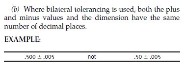
3_v1ctes.jpg


However, when it comes to inspection of the part:
1. Will the 1/10th rule of thumb apply to the total value of the tolerance (i.e. 10% of 0.02" = 0.002"); meaning that the measurement system only needs to be accurate up to the third decimal, or
2. Would the trailing zeroes/number of decimals be overriding it (i.e. the measurement system will have to be able to measure up to the fifth decimal)?

Worse if I have a dimension which is from the 32th fraction, for example, 1.40625". Following ASME Y14.5 rules, I suppose the tolerance would be written as +/-0.01000". What about the inspection then? Six-decimal accuracy on the measuring system?

Drawing-wise, I can just label it as per the actual 3D dimension and the ASME rules just to be true to the part and the rules. However, I would think that this will have huge implication on manufacturing and inspection cost.

I'm sure that many of the forumers would have encountered this in real life. I would appreciate to hear on how this is case is being handled.

------------------------------------
Also on another related topic:

With regards to the snapshot below, would it also be acceptable for the other way around? I suppose the implication would be similar to my question above.
1. Basic Dimension: 1.625"
2. Positional Tolerance: Diameter 0.02" (no trailing zeroes to match the Basic Dimension)
1_qqv1da.jpg

2_c3h00w.jpg
 
Replies continue below

Recommended for you

I agree that it really only comes into play when the parts are falling close to the LSL/USL, but again if you're not measuring to the level of precision as defined on the drawing, how can you ensure that you're not inadvertently shipping bad parts, or rejecting good parts? The measurement system has to be able to reliably distinguish & report the part variation at that level. This is where the automotive requirement of NDC > 5 on a GR&R comes into play, to ensure your measurement system is capable.


Burunduk said:
I don't think anyone would insist on such measurement when the requirement is 1.29+/-0.02

Neither would I, because in this example the requirement explicitly defines the precision at 2 decimals, which is what would be recorded on the layout. You should then choose a measurement system that reports to at least 3 decimals (10%) to ensure variation can accurately captured at your boundary cases.


Then, what should dictate the accuracy of the measurement system? I say it's the width of the tolerance band, not the number of decimal places on the drawing.

The ability to accurately & reliably distinguish part variation at the level required, width of the tolerance band is irrelevant.
A spec of 10.524 +/- 1.000, or 10.524 +/- 0.001, would both require a measurement system capable of reporting to the 4 decimal at a minimum to ensure part conformance at the boundary conditions. I'm not arguing that it's practical (that's a conversation you need to have with the customer), but you cannot ensure part conformance if your measurement system is incapable of measuring variation at/beyond the defined resolution.
 
The accuracy of the measurement systems should be dictated by epsilon, the amount of uncertainty allocated for the measurements. Even with a large tolerance, if the desire to accept variations close to the tolerance then the epsilon becomes smaller and the measurement has to become more precise and accurate.

The larger the epsilon the greater the rate of rejection of parts that meet the requirement.

For a process that is producing a statistically uniform distribution, a 5% or a 10% allowance for gagemakers is going to reject 5% or 10% of the usable product, respectively.

If the process has a perfectly normal/Gaussian distribution and the tolerances are set to the 3σ limits, then a 5% gagemakers allowance could reject ~0.17% and 10% gagemakers allowance could reject ~0.42% of usable product.

If the tolerance limits are at the 1σ values then the 5% gagemakers allowance could reject ~2.5% and the ~10% gagemakers allowance could reject 5% of usable product.

My guess is that the gagemakers who recommend those allowances are in industries that dependably use design tolerances that are 3σ or more than the production variations for those features. By the time 6σ ranges are in play, the numbers of unwanted rejections is in the few parts per million.

But, if one doesn't have information about the process it's difficult to know just how much is wasted. All this goes worse if the 1σ variation is larger than the tolerance or if the variation distribution is skewed or the mean is not centered on the tolerance zone.
 
Burunduk said:
But the Y14.5 standard explicitly tells you to treat it the same as +/-0.0200...0, so there must be some other reason.

That's what I was asking clarification on in one of my previous posts. My interpretation was that 5.4 defines the limits as extending to infinity, in order to allow for the limit to be expanded to match the precision indicated by the nominal, but wasn't sure if that was correct.

Mech1595 said:
Burunduk,

Does this section 5.4 not support the idea that limit decimals are driven by the resolution of the nominal [edit: in this example], as the limits are defined to infinity?
What am I missing?

E.g
......

 
Mech said:
My interpretation was that 5.4 defines the limits as extending to infinity, in order to allow for the limit to be expanded to match the precision indicated by the nominal, but wasn't sure if that was correct.

What you should understand from 5.4 is that as far as a tolerance specification is concerned, there are hard limits that can't be violated, regardless of the number of decimals on the drawing.

So the clarification you are looking for is this: "in order to allow for the limit to be expanded to match the precision indicated by the nominal" is not right. It need not to be expanded depending on the number of digits in the nominal or the tolerance, as it is already expanded infinitely by definition. Otherwise, "12.2 means 12.20...0" would not be the case, since 12.2 as a limit would not have the same meaning as 12.20000.

What should allow for accepting a small amount of slightly out of tolerance parts (by using not infinitely accurate metrology equipment), is quality practices that relate between the size of the tolerance and the measurement accuracy level required.


3DDave said:
For a process that is producing a statistically uniform distribution, a 5% or a 10% allowance for gagemakers is going to reject 5% or 10% of the usable product, respectively.

This is not entirely correct.
It sounds like it would be correct if one chooses a policy that would reject all out of tolerance parts. But the most strict policy is not always the best for every single task. For fixed size gages there are several gage tolerancing policies covered by ASME Y14.43. Some are stricter, and some are more permissive towards accepting some out of tolerance parts to allow more within-tolerance parts to pass.


Yes, one can choose a policy to lie to customers about the out-of-tolerance products your company is shipping. That sounds like an out-of-control process from an incapable manufacturing group that lied to get a contract.

It's one thing to "inspect quality in" and another to "inspect defective parts into the supply chain."

You do you.
 
While awaiting further reply, I'll note that if a customer agrees to off-drawing tolerance increases to accept more parts, that is simply undocumented tolerance increase and so the practice would accept in-tolerance parts.
 
3DDave,
Out of 4 gage tolerancing policies outlined in ASME Y14.43, one matches your strict approach. The other policies allow some borderline out of tolerance variation on the inspected part to pass inspection as result of the gage/fixture tolerancing strategy.

One counter-example to the strict approach is this:

ASME Y14.43-2011 said:
4.3.2 Optimistic Tolerancing. Optimistic tolerancing is the policy of tolerancing gages that ensures all part features within tolerance that are gaged are accepted by the gage. This is accomplished by applying gagemakers’
tolerances, wear allowances, measurement uncertainties, and form controls all outside of the workpiece limits of size and geometric control. Gage tolerances subtract material from the gage beginning at the limit [e.g., MMC
or virtual condition (MMC concept) of the feature being gaged]. Gages produced in accordance with this policy will accept part features that are within tolerance, reject most features not within tolerance, and accept a small percentage of borderline part features that are technically not within tolerance.

Again, those small deviations outside the spec are limited by gagemakers' tolerances which are an order of magnitude smaller than the allowed variation for the part feature. There are applications that can't tolerate this, but not every application is like that.

If you think this means lying to the customer, blame the committee and write them a complaint.

________

Mech1595,
Does my clarification make sense to you?
I assumed that by "allow for the limit to be expanded to match the precision indicated by the nominal" as you originally wrote you meant expanding the number of decimal places considered by the variation limit, not expanding the geometric limit.
The geometric limits defined by the dimension and tolerance are hard and rigid, but quality practices usually allow some leakage through those limits. The level of that leakage should not depend on the number of decimals on the drawing. It has no reason to, and it would be in conflict with Y14.5.
 
This is accomplished by applying gagemakers’tolerances, wear allowances, measurement uncertainties, and form controls all outside of the workpiece limits of size and geometric control.

That's not optimistic, that's just increasing the acceptable variation without increasing the allowable tolerance. No one needs to standardize that; cheaters will do that all on their own.

 
Recall that the gaging standard is for the benefit of selling gages. If a gage maker says "This can accept 5-10% more parts" because of these rules but the rules aren't clear as to the risk and tend, instead, to paper over the risk with "a small percentage of borderline part features", which actually means accepting 100% of the parts that exceed the tolerances by however much the gage maker can manage to slip in.

Of course the committee wants that in the standard. Their priority is selling gages and gage making services. They need buy-in from the maximum number of gage makers and this gives those charged with including unusable parts as acceptable output a way to do so.

If the design can stand a larger tolerance, change the documentation to show that. Doing this under-the-table crap is dishonest and it annoys me that it is not put in an "avoid these practices" section.
 
Burunduk,

Burunduk said:
Does my clarification make sense to you?
I assumed that by "allow for the limit to be expanded to match the precision indicated by the nominal" as you originally wrote you meant expanding the number of decimal places considered by the variation limit, not expanding the geometric limit.

Yes thank you, that's exactly what I meant but was struggling to articulate.
 
Status
Not open for further replies.

Part and Inventory Search

Sponsor